Pressure Systems, Inc. | 9016 Upgrade Instructions |
(5)Carefully guide the LEDs (on the PC-322 board) into their respective holes in the scanner chassis. Ensure that all cables and tubing are not crimped or restricted and attach the PC- 322/323 boards to the chassis with the three (3) Phillips-head screws through the top plate (that were previously removed and saved). Do not tighten completely.
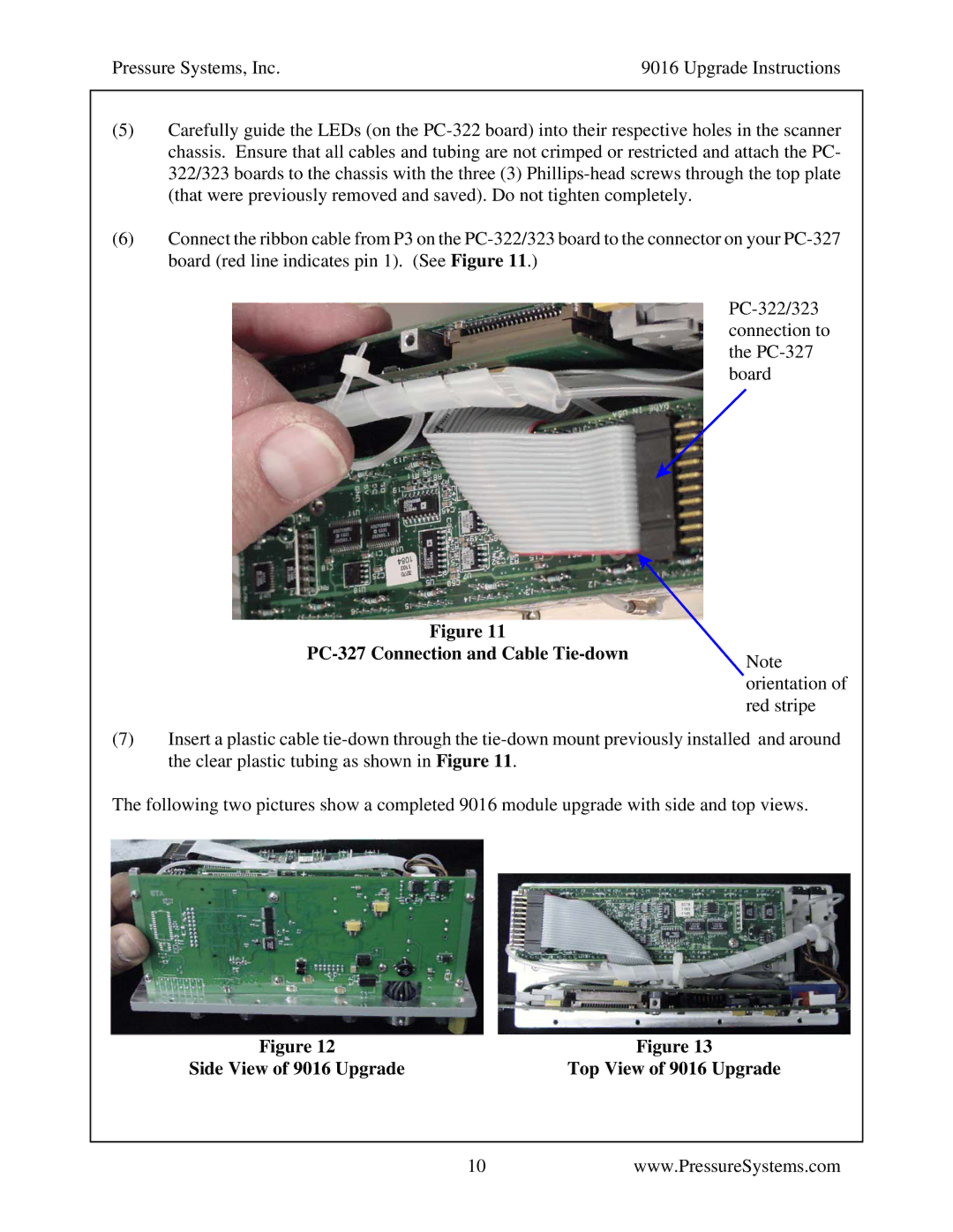
(6)Connect the ribbon cable from P3 on the PC-322/323 board to the connector on your PC-327 board (red line indicates pin 1). (See Figure 11.)
PC-322/323 connection to the PC-327 board
Figure 11
PC-327 Connection and Cable Tie-downNote
orientation of
red stripe
(7)Insert a plastic cable tie-down through the tie-down mount previously installed and around the clear plastic tubing as shown in Figure 11.
The following two pictures show a completed 9016 module upgrade with side and top views.
Figure 12 | Figure 13 |
Side View of 9016 Upgrade | Top View of 9016 Upgrade |
10www.PressureSystems.com