I V . O P E R A T I O N
LIFT SYSTEM OPERATION
WARNING! The lift system is intended for the transport of mobility devices only. The mobility device must be unoccupied before operating the lift.
WARNING! Do not exceed the load limits of your vehicle or hitch system as specified by the vehicle manufacturer.
WARNING! Use extreme caution when driving with the lift installed on your vehicle. Be aware that the lift extends away from the back of the vehicle and extra clearance is needed when backing up, turning, parking, or driving through driveway entrances/exits. Drive slowly when negotiating pot holes, road bumps, and railroad tracks.
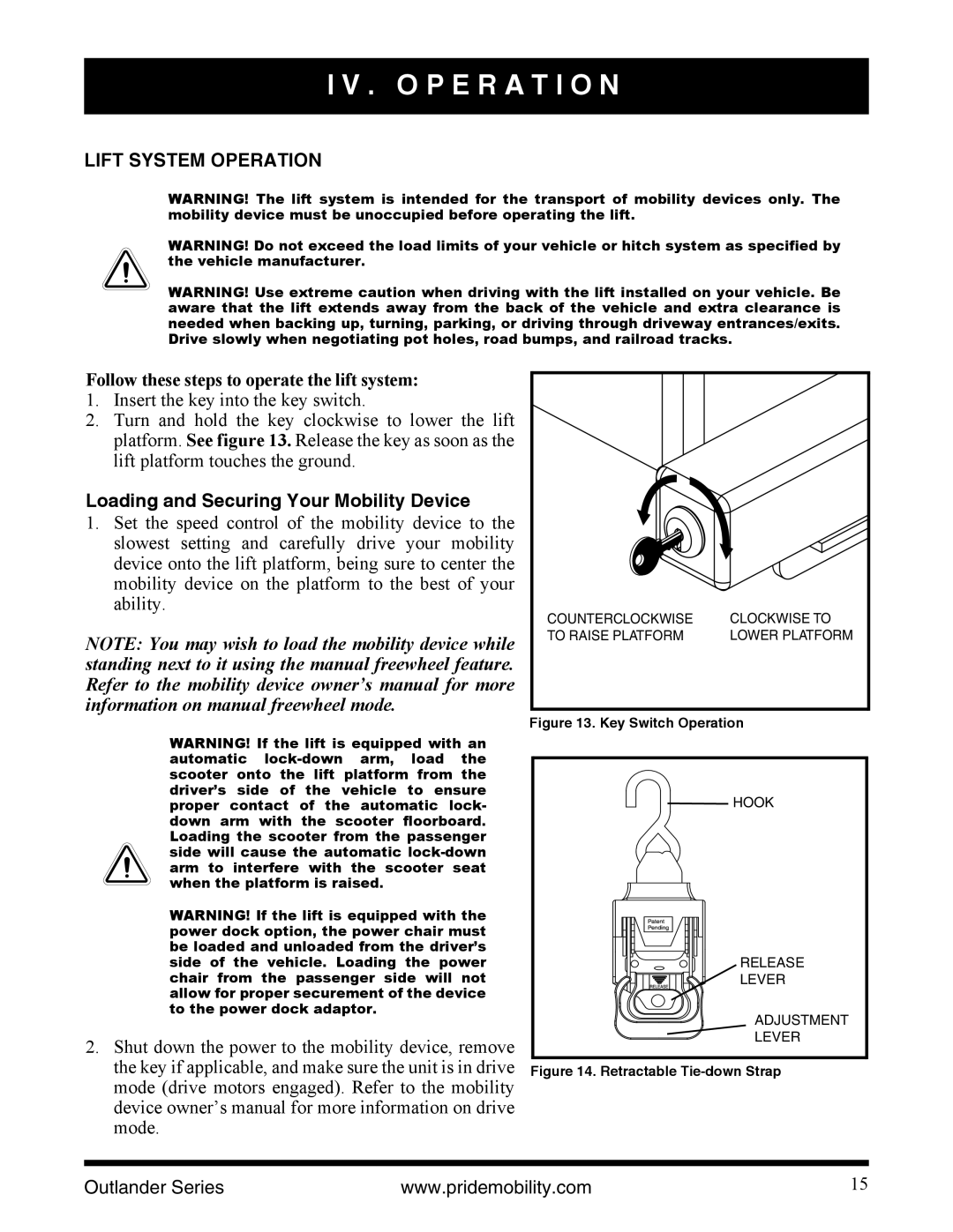
Follow these steps to operate the lift system:
1.Insert the key into the key switch.
2.Turn and hold the key clockwise to lower the lift platform. See figure 13. Release the key as soon as the lift platform touches the ground.
Loading and Securing Your Mobility Device
1.Set the speed control of the mobility device to the slowest setting and carefully drive your mobility device onto the lift platform, being sure to center the mobility device on the platform to the best of your ability.
NOTE: You may wish to load the mobility device while standing next to it using the manual freewheel feature. Refer to the mobility device owner’s manual for more information on manual freewheel mode.
WARNING! If the lift is equipped with an automatic
WARNING! If the lift is equipped with the power dock option, the power chair must be loaded and unloaded from the driver’s side of the vehicle. Loading the power chair from the passenger side will not allow for proper securement of the device to the power dock adaptor.
2.Shut down the power to the mobility device, remove the key if applicable, and make sure the unit is in drive mode (drive motors engaged). Refer to the mobility device owner’s manual for more information on drive mode.
COUNTERCLOCKWISE | CLOCKWISE TO |
TO RAISE PLATFORM | LOWER PLATFORM |
Figure 13. Key Switch Operation
![]()
![]() HOOK
HOOK
RELEASE
LEVER
ADJUSTMENT
LEVER
Figure 14. Retractable Tie-down Strap
Outlander Series | www.pridemobility.com | 15 |