VENTILATION AIR

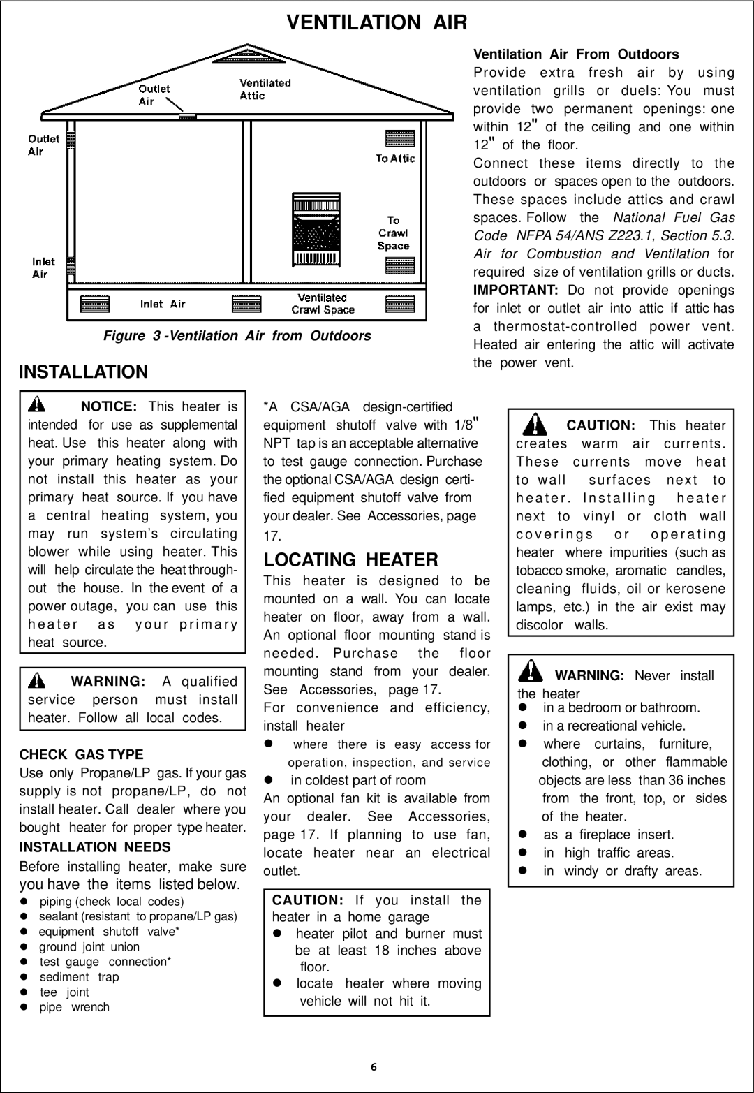
Figure 3 -Ventilation Air from Outdoors

INSTALLATION

Ventilation Air From Outdoors

Provide extra fresh air by using ventilation grills or duels: You must provide two permanent openings: one within 12" of the ceiling and one within 12" of the floor.

Connect these items directly to the outdoors or spaces open to the outdoors. These spaces include attics and crawl spaces. Follow the National Fuel Gas Code NFPA 54/ANS Z223.1, Section 5.3. Air for Combustion and Ventilation for required size of ventilation grills or ducts. IMPORTANT: Do not provide openings for inlet or outlet air into attic if attic has

athermostat-controlled power vent. Heated air entering the attic will activate the power vent.

NOTICE: This heater is intended for use as supplemental heat. Use this heater along with your primary heating system. Do not install this heater as your primary heat source. If you have a central heating system, you may run system’s circulating blower while using heater. This will help circulate the heat through- out the house. In the event of a power outage, you can use this h e a t e r a s y o u r p r i m a r y heat source.

WARNING: A qualified service person must install heater. Follow all local codes.

CHECK GAS TYPE

Use only Propane/LP gas. If your gas supply is not propane/LP, do not install heater. Call dealer where you bought heater for proper type heater.

INSTALLATION NEEDS

Before installing heater, make sure

you have the items listed below.

piping (check local codes)

sealant (resistant to propane/LP gas) equipment shutoff valve*

ground joint union

test gauge connection* sediment trap

tee joint pipe wrench

*A CSA/AGA design-certified equipment shutoff valve with 1/8" NPT tap is an acceptable alternative to test gauge connection. Purchase the optional CSA/AGA design certi- fied equipment shutoff valve from your dealer. See Accessories, page 17.

LOCATING HEATER

This heater is designed to be mounted on a wall. You can locate heater on floor, away from a wall. An optional floor mounting stand is needed. Purchase the floor mounting stand from your dealer. See Accessories, page 17.

For convenience and efficiency, install heater

where there is easy access for

operation, inspection, and service

in coldest part of room

An optional fan kit is available from your dealer. See Accessories, page 17. If planning to use fan, locate heater near an electrical outlet.

CAUTION: If you install the heater in a home garage

heater pilot and burner must be at least 18 inches above floor.

locate heater where moving vehicle will not hit it.

CAUTION: This heater creates warm air currents.

These

currents move heat

to wall

surfaces

next

to

h e a t e r . I n s t a l l i n g

h e a t e r

next

to

vinyl

or

cloth

wall

c o v e r i n g s

o r

o p e r a t i n g

heater

where impurities

(such as

tobacco smoke, aromatic

candles,

cleaning

fluids, oil or kerosene

lamps, etc.) in the air exist may discolor walls.

WARNING: Never install

the heater

in a bedroom or bathroom. in a recreational vehicle. where curtains, furniture, clothing, or other flammable objects are less than 36 inches from the front, top, or sides of the heater.

as a fireplace insert. in high traffic areas.

in windy or drafty areas.

6

Page 6
Image 6
Procom ML300HGA, ML300TGA installation manual Ventilation AIR, Locating Heater, Check GAS Type, Installation Needs

ML300HGA, ML300TGA specifications

The Procom ML300HGA and ML300TGA are advanced communication solutions designed for an array of applications, particularly in sectors requiring robust and reliable wireless connectivity. Both models are designed to enhance operational efficiency through enhanced performance and pertinent features.

The ML300HGA model is tailored for high-gain applications, providing exceptional signal strength in demanding environments. This makes it an ideal choice for remote monitoring, industrial communication, and public safety operations where optimal signal reception is critical. It supports multiple frequency bands, including VHF and UHF, allowing flexibility in deployment across various networks.

Equipped with advanced antenna technology, the ML300HGA is designed to minimize noise and interference, ensuring clear communication even in congested frequencies. The rugged construction of this model makes it resilient to harsh environmental conditions—be it extreme temperatures, moisture, or physical impacts, thus increasing its longevity and reliability in the field.

On the other hand, the ML300TGA is designed for versatility and is particularly favored for its compact design and lightweight structure. This model is optimized for applications that require portability without compromising on performance. It is ideal for temporary installations or scenarios where mobility and adaptability are paramount.

Key features of the ML300TGA include multiple input and output options, allowing easy integration with various communication systems. Its modular design allows for easy upgrades and expansions, which is beneficial as organizational needs evolve.

Both models incorporate the latest advancements in antenna design technology, such as low Vswr (voltage standing wave ratio) and high efficiency, which translates to better bandwidth utilization. They also feature weather-resistant capabilities, ensuring functionality in diverse environments while maintaining signal integrity.

Moreover, these devices are designed with user-friendly interfaces, ensuring ease of operation, maintenance, and troubleshooting. The proprietary algorithms deployed in the ML300 series enhance signal processing capabilities, allowing for the management of multiple connections while optimizing performance.

When considering wireless communication equipment, the Procom ML300HGA and ML300TGA provide premier options that combine cutting-edge technology with practical features, addressing the needs of professionals in various fields. From industrial applications to public safety, these models are engineered to deliver dependable, high-quality performance in every situation.