ELECTRICAL AND SIGNAL CONNECTIONS
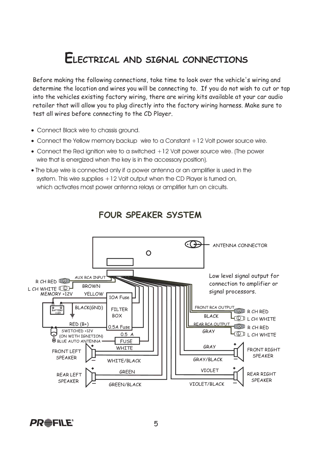
Before making the following connections, take time to look over the vehicle's wiring and determine the location and wires you will be connecting to. If you do not wish to cut or tap into the vehicles existing factory wiring, there are wiring kits available at your car audio retailer that will allow you to plug directly into the factory wiring harness. Make sure to test all wires before connecting to the CD Player.
!Connect Black wire to chassis ground.
!Connect the Yellow memory backup wire to a Constant +12 Volt power source wire.
!Connect the Red ignition wire to a switched +12 Volt power source wire. (The power wire that is energized when the key is in the accessory position).
!The blue wire is connected only if a power antenna or an amplifier is used in the system. This wire supplies +12 Volt output when the CD Player is turned on, which activates most power antenna relays or amplifier turn on circuits.
FOUR SPEAKER SYSTEM
ANTENNA CONNECTOR
R CH RED ![]() R
R![]()
AUX RCA INPUT
Low level signal output for
connection to amplifier or
LBROWN
L CH WHITE ![]()
![]()
MEMORY +12V | YELLOW | 1OA Fuse | |
|
| ||
+ - | BLACK(GND) | FILTER | |
BATTERY |
| ||
+12V |
| BOX | |
|
| ||
RED (B+) | 0.5A Fuse | ||
SWITCHED +12V | |||
0.5 A | |||
(ON WITH IGNITION) | |||
BLUE AUTO ANTENNA | FUSE | ||
| + | WHITE | |
FRONT LEFT | |||
| |||
signal processors.
FRONT RCA OUTPUT | R | R CH RED | |
BLACK | |||
L | L CH WHITE | ||
REAR RCA OUTPUT | |||
R | R CH RED | ||
|
GRAY
L![]() L CH WHITE
L CH WHITE
GRAY +
FRONT RIGHT
SPEAKER | WHITE/BLACK |
|
GRAY/BLACK
SPEAKER
| + |
REAR LEFT | GREEN |
| |
SPEAKER | GREEN/BLACK |
|
VIOLET +
VIOLET/BLACK
REAR RIGHT
SPEAKER
5
