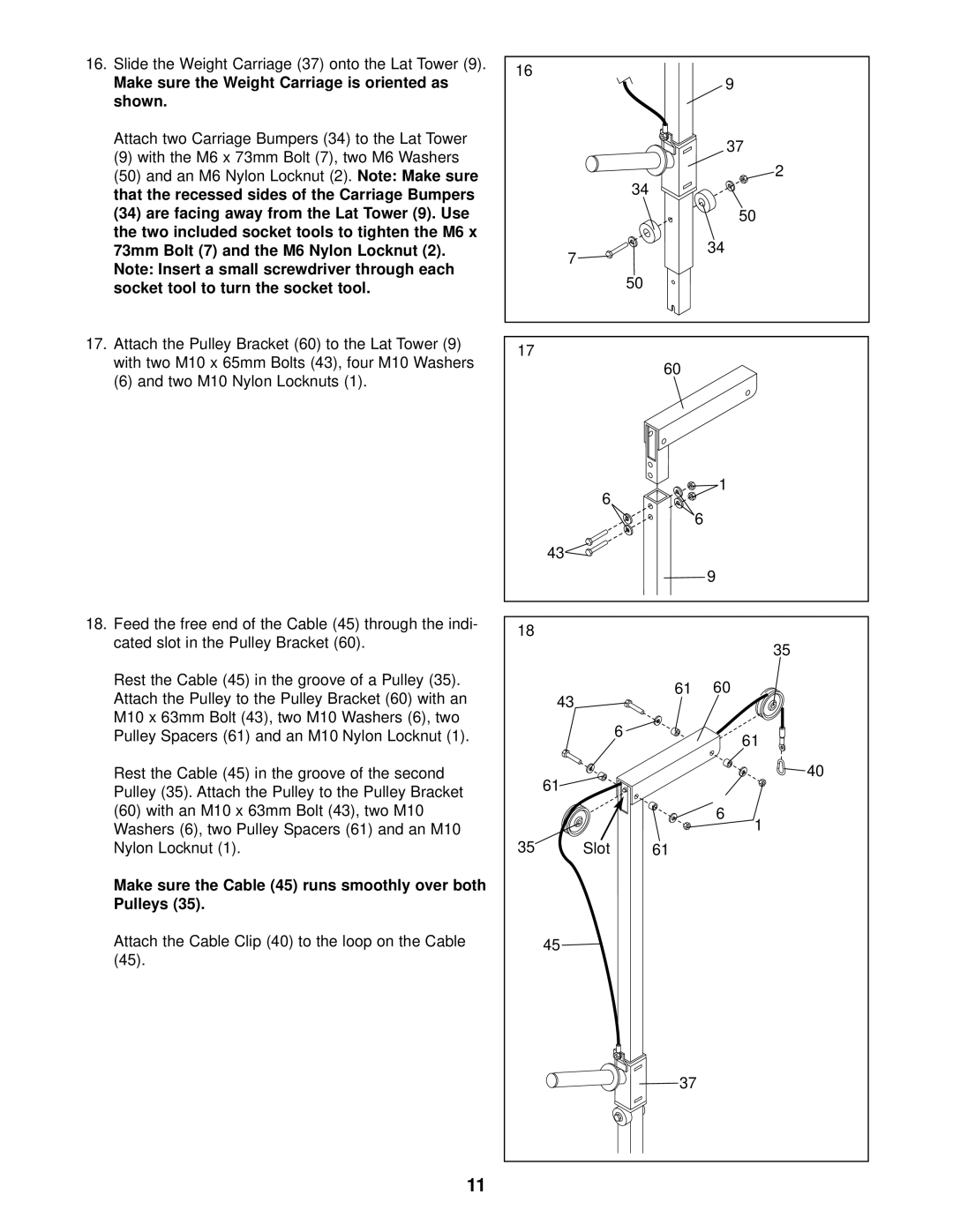
16. Slide the Weight Carriage (37) onto the Lat Tower (9). |
Make sure the Weight Carriage is oriented as |
shown. |
Attach two Carriage Bumpers (34) to the Lat Tower |
(9) with the M6 x 73mm Bolt (7), two M6 Washers |
(50) and an M6 Nylon Locknut (2). Note: Make sure |
that the recessed sides of the Carriage Bumpers |
16
9
37
![]() 2
2
34
(34) are facing away from the Lat Tower (9). Use |
the two included socket tools to tighten the M6 x |
73mm Bolt (7) and the M6 Nylon Locknut (2). |
Note: Insert a small screwdriver through each |
7
50
34
socket tool to turn the socket tool. |
17. Attach the Pulley Bracket (60) to the Lat Tower (9) |
with two M10 x 65mm Bolts (43), four M10 Washers |
(6) and two M10 Nylon Locknuts (1). |
18.Feed the free end of the Cable (45) through the indi- cated slot in the Pulley Bracket (60).
Rest the Cable (45) in the groove of a Pulley (35). Attach the Pulley to the Pulley Bracket (60) with an M10 x 63mm Bolt (43), two M10 Washers (6), two Pulley Spacers (61) and an M10 Nylon Locknut (1).
50
17
60
1
6![]()
![]() 6
6
43![]()
9
18
35
61 60
43 |
|
6 | 61 |
|
Rest the Cable (45) in the groove of the second Pulley (35). Attach the Pulley to the Pulley Bracket
61![]()
40
(60)with an M10 x 63mm Bolt (43), two M10 Washers (6), two Pulley Spacers (61) and an M10 Nylon Locknut (1).
Make sure the Cable (45) runs smoothly over both Pulleys (35).
Attach the Cable Clip (40) to the loop on the Cable (45).
6
35 Slot 61
45
37
1
11