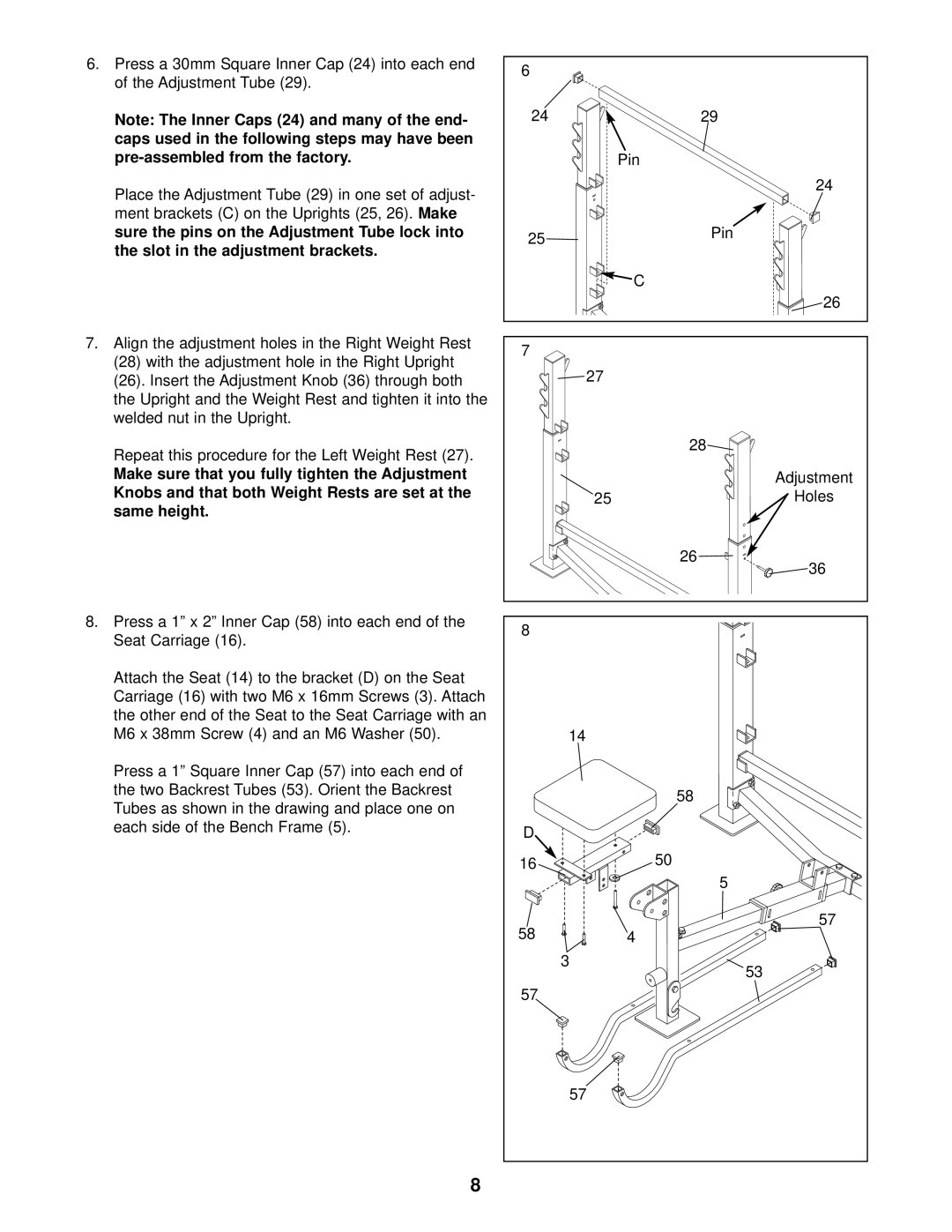
6.Press a 30mm Square Inner Cap (24) into each end of the Adjustment Tube (29).
Note: The Inner Caps (24) and many of the end- caps used in the following steps may have been
Place the Adjustment Tube (29) in one set of adjust- ment brackets (C) on the Uprights (25, 26). Make sure the pins on the Adjustment Tube lock into the slot in the adjustment brackets.
7.Align the adjustment holes in the Right Weight Rest
(28)with the adjustment hole in the Right Upright
(26).Insert the Adjustment Knob (36) through both the Upright and the Weight Rest and tighten it into the welded nut in the Upright.
Repeat this procedure for the Left Weight Rest (27).
Make sure that you fully tighten the Adjustment Knobs and that both Weight Rests are set at the same height.
8.Press a 1” x 2” Inner Cap (58) into each end of the Seat Carriage (16).
Attach the Seat (14) to the bracket (D) on the Seat Carriage (16) with two M6 x 16mm Screws (3). Attach the other end of the Seat to the Seat Carriage with an M6 x 38mm Screw (4) and an M6 Washer (50).
Press a 1” Square Inner Cap (57) into each end of the two Backrest Tubes (53). Orient the Backrest Tubes as shown in the drawing and place one on each side of the Bench Frame (5).
6 |
|
24 | 29 |
| Pin |
| 24 |
25 | Pin |
| |
| C |
| 26 |
7 |
|
27 |
|
| 28 |
| Adjustment |
25 | Holes |
| 26 |
| 36 |
8 |
|
14 |
|
| 58 |
D |
|
16 | 50 |
| 5 |
58 | 57 |
4 | |
3 | 53 |
| |
57 |
|
57 |
|
8