.
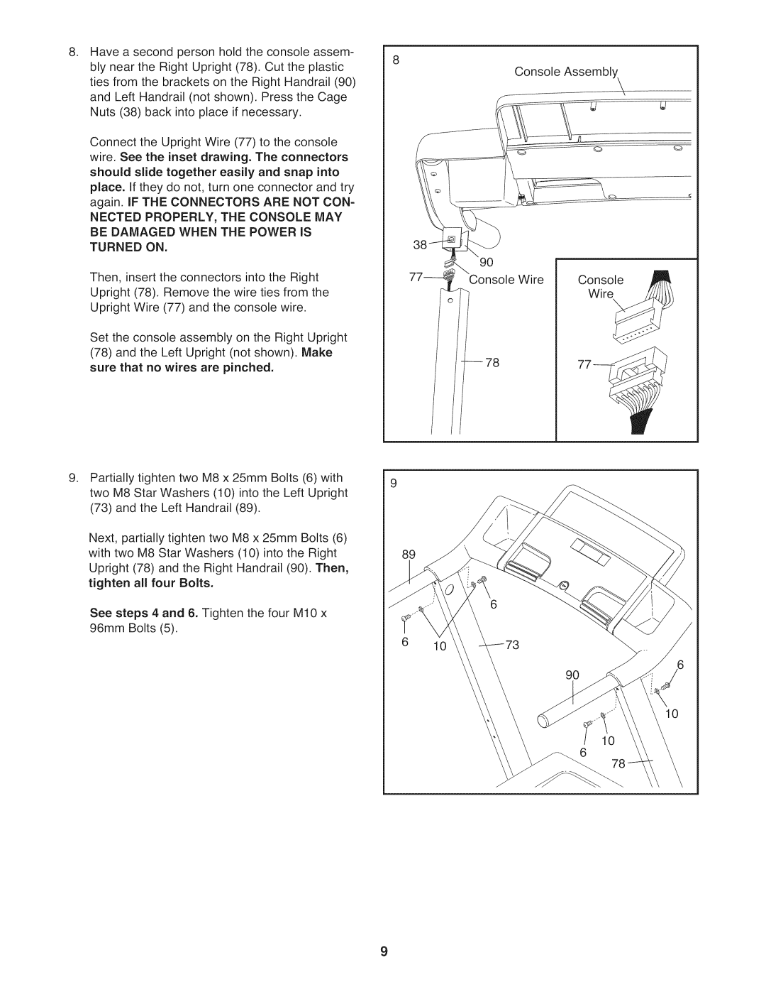
Have a second person hold the console assem- bly near the Right Upright (78). Cut the plastic ties from the brackets on the Right Handrail (90) and Left Handrail (not shown). Press the Cage Nuts (38) back into place if necessary.
Connect the Upright Wire (77) to the console wire. See the inset drawing. The connectors should slide together easily and snap into place. If they do not, turn one connector and try again. IF THE CONNECTORS ARE NOT CON-
NECTED PROPERLY, THE CONSOLE MAY BE DAMAGED WHEN THE POWER IS
TURNED ON.
Then, insert the connectors into the Right Upright (78). Remove the wire ties from the Upright Wire (77) and the console wire.
Console Assembly\
f
0
Q
3
Console /1_
Set the console assembly on the Right Upright
(78)and the Left Upright (not shown). Make sure that no wires are pinched.
77_Console Wire
Wire_
.
Partially tighten two M8 x 25mm Bolts (6) with two M8 Star Washers (10) into the Left Upright (73) and the Left Handrail (89).
Next, partially tighten two M8 x 25mm Bolts (6) with two M8 Star Washers (10) into the Right Upright (78) and the Right Handrail (90). Then, tighten all four Bolts.
See steps 4 and 6. Tighten the four M10 x 96mm Bolts (5).
/ /_ | 78 | 77_ |
89
78
9