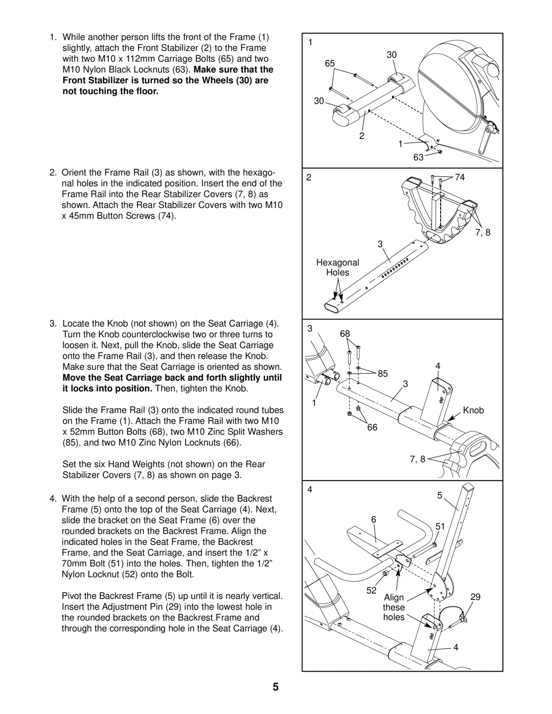
1.While another person lifts the front of the Frame (1) slightly, attach the Front Stabilizer (2) to the Frame with two M10 x 112mm Carriage Bolts (65) and two
M10 Nylon Black Locknuts (63). Make sure that the
Front Stabilizer is turned so the Wheels (30) are not touching the floor.
2.Orient the Frame Rail (3) as shown, with the hexago- nal holes in the indicated position. Insert the end of the Frame Rail into the Rear Stabilizer Covers (7, 8) as shown. Attach the Rear Stabilizer Covers with two M10 x 45mm Button Screws (74).
3.Locate the Knob (not shown) on the Seat Carriage (4). Turn the Knob counterclockwise two or three turns to loosen it. Next, pull the Knob, slide the Seat Carriage onto the Frame Rail (3), and then release the Knob. Make sure that the Seat Carriage is oriented as shown.
Move the Seat Carriage back and forth slightly until
it locks into position. | Then, tighten the Knob. |
Slide the Frame Rail (3) onto the indicated round tubes on the Frame (1). Attach the Frame Rail with two M10
x 52mm Button Bolts (68), two M10 Zinc Split Washers (85), and two M10 Zinc Nylon Locknuts (66).
Set the six Hand Weights (not shown) on the Rear Stabilizer Covers (7, 8) as shown on page 3.
4. With the help of a second person, slide the Backrest Frame (5) onto the top of the Seat Carriage (4). Next, slide the bracket on the Seat Frame (6) over the rounded brackets on the Backrest Frame. Align the indicated holes in the Seat Frame, the Backrest
Frame, and the Seat Carriage, and insert the 1/2” x 70mm Bolt (51) into the holes. Then, tighten the 1/2” Nylon Locknut (52) onto the Bolt.
Pivot the Backrest Frame (5) up until it is nearly vertical. Insert the Adjustment Pin (29) into the lowest hole in the rounded brackets on the Backrest Frame and
through the corresponding hole in the Seat Carriage (4).
1 |
| |
| 30 |
|
| 65 |
|
| 30 |
|
| 2 |
|
| 1 |
|
|
| 63 |
2 |
| 74 |
|
| 7, 8 |
| 3 |
|
| Hexagonal |
|
| Holes |
|
3 | 68 |
|
|
| |
| 85 | 4 |
|
| |
| 3 |
|
| 1 | Knob |
|
| |
| 66 |
|
|
| 7, 8 |
4 |
| 5 |
|
| |
| 6 | 51 |
|
| |
| 52 | 29 |
| Align | |
| these |
|
| holes |
|
|
| 4 |
5