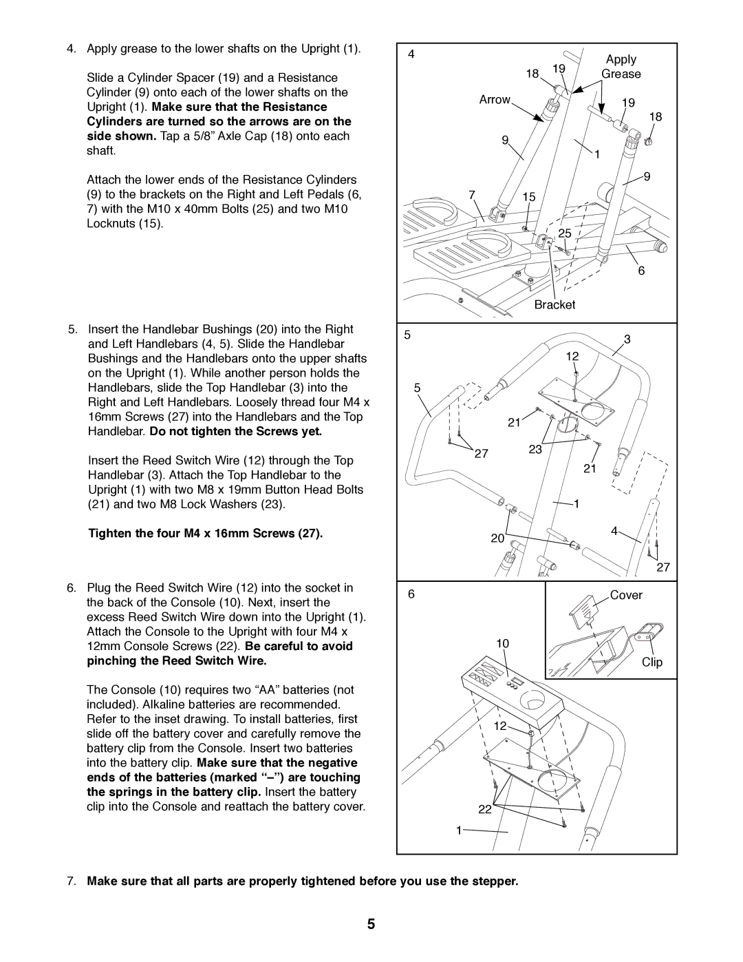
4.Apply grease to the lower shafts on the Upright (1).
Slide a Cylinder Spacer (19) and a Resistance Cylinder (9) onto each of the lower shafts on the Upright (1). Make sure that the Resistance
Cylinders are turned so the arrows are on the side shown. Tap a 5/8Ó Axle Cap (18) onto each shaft.
Attach the lower ends of the Resistance Cylinders
(9) to the brackets on the Right and Left Pedals (6, 7) with the M10 x 40mm Bolts (25) and two M10 Locknuts (15).
5.Insert the Handlebar Bushings (20) into the Right and Left Handlebars (4, 5). Slide the Handlebar Bushings and the Handlebars onto the upper shafts on the Upright (1). While another person holds the Handlebars, slide the Top Handlebar (3) into the Right and Left Handlebars. Loosely thread four M4 x 16mm Screws (27) into the Handlebars and the Top Handlebar. Do not tighten the Screws yet.
Insert the Reed Switch Wire (12) through the Top Handlebar (3). Attach the Top Handlebar to the Upright (1) with two M8 x 19mm Button Head Bolts (21) and two M8 Lock Washers (23).
Tighten the four M4 x 16mm Screws (27).
6.Plug the Reed Switch Wire (12) into the socket in the back of the Console (10). Next, insert the excess Reed Switch Wire down into the Upright (1). Attach the Console to the Upright with four M4 x 12mm Console Screws (22). Be careful to avoid pinching the Reed Switch Wire.
The Console (10) requires two ÒAAÓ batteries (not included). Alkaline batteries are recommended. Refer to the inset drawing. To install batteries, first slide off the battery cover and carefully remove the battery clip from the Console. Insert two batteries into the battery clip. Make sure that the negative ends of the batteries (marked ÒÐÓ) are touching the springs in the battery clip. Insert the battery clip into the Console and reattach the battery cover.
4 |
|
| Apply |
|
| 19 | |
| 18 | Grease | |
Arrow |
|
| 19 |
|
|
| 18 |
9 |
|
|
|
|
|
| 1 |
|
|
| 9 |
7 | 15 |
|
|
|
| 25 |
|
|
|
| 6 |
| Bracket |
| |
5 |
|
| 3 |
|
|
| |
|
| 12 |
|
5 |
|
|
|
21 |
|
|
|
27 | 23 |
|
|
|
|
| |
|
|
| 21 |
|
| 1 |
|
20 |
|
| 4 |
|
|
| |
|
|
| 27 |
6 |
|
| Cover |
10 |
|
|
|
|
|
| Clip |
12 |
|
|
|
22 |
|
|
|
1 |
|
|
|
7.Make sure that all parts are properly tightened before you use the stepper.
5