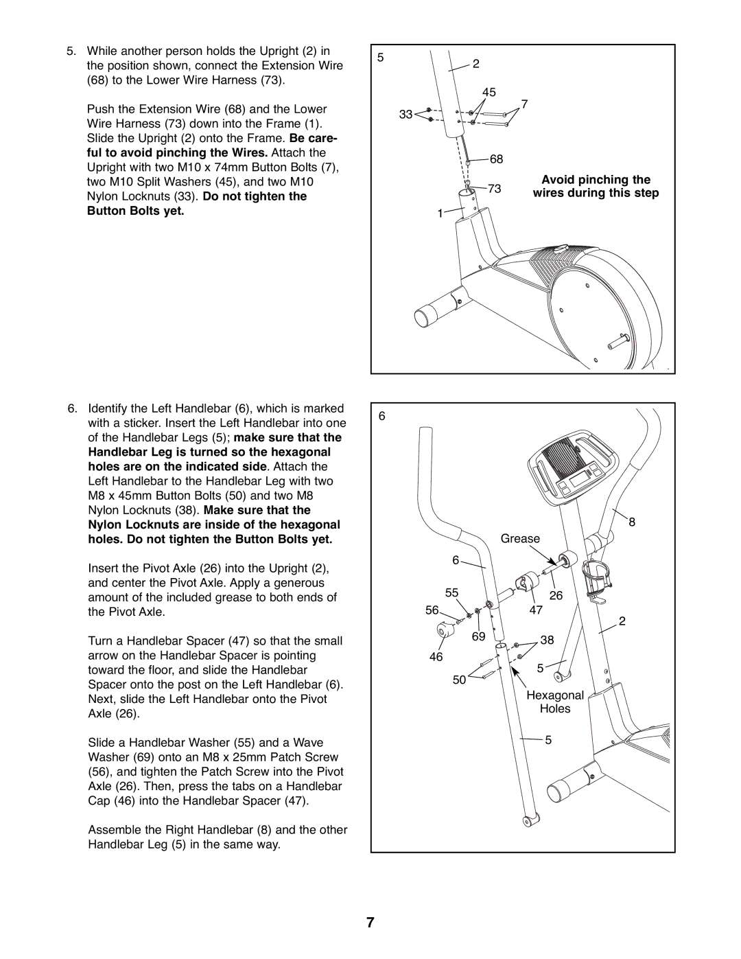
5. While another person holds the Upright (2) in | 5 | 2 |
|
|
the position shown, connect the Extension Wire |
|
| ||
|
|
| ||
(68) to the Lower Wire Harness (73). |
| 45 |
| |
|
| 7 | ||
Push the Extension Wire (68) and the Lower | 33 |
|
| |
|
|
| ||
Wire Harness (73) down into the Frame (1). |
|
|
| |
|
|
|
| |
Slide the Upright (2) onto the Frame. Be care- |
|
|
|
|
ful to avoid pinching the Wires. Attach the |
|
| 68 |
|
Upright with two M10 x 74mm Button Bolts (7), |
|
|
| |
|
|
| Avoid pinching the | |
two M10 Split Washers (45), and two M10 |
|
| 73 | |
Nylon Locknuts (33). Do not tighten the |
|
| wires during this step | |
|
|
| ||
Button Bolts yet. | 1 |
|
|
|
6. Identify the Left Handlebar (6), which is marked | 6 |
|
|
|
with a sticker. Insert the Left Handlebar into one |
|
|
| |
|
|
|
| |
of the Handlebar Legs (5); make sure that the |
|
|
|
|
Handlebar Leg is turned so the hexagonal |
|
|
|
|
holes are on the indicated side. Attach the |
|
|
|
|
Left Handlebar to the Handlebar Leg with two |
|
|
|
|
M8 x 45mm Button Bolts (50) and two M8 |
|
|
|
|
Nylon Locknuts (38). Make sure that the |
|
|
| 8 |
Nylon Locknuts are inside of the hexagonal |
|
|
| |
holes. Do not tighten the Button Bolts yet. |
|
| Grease | |
Insert the Pivot Axle (26) into the Upright (2), | 6 |
|
|
|
|
|
|
| |
and center the Pivot Axle. Apply a generous | 55 |
|
| 26 |
amount of the included grease to both ends of |
|
| ||
the Pivot Axle. | 56 |
|
| 47 |
|
|
|
| 2 |
Turn a Handlebar Spacer (47) so that the small |
| 69 |
| 38 |
|
|
| ||
arrow on the Handlebar Spacer is pointing | 46 |
|
| 5 |
toward the floor, and slide the Handlebar | 50 |
|
| |
Spacer onto the post on the Left Handlebar (6). |
|
|
| |
|
|
| Hexagonal | |
Next, slide the Left Handlebar onto the Pivot |
|
|
| |
|
|
| Holes | |
Axle (26). |
|
|
| |
|
|
|
| |
Slide a Handlebar Washer (55) and a Wave |
|
|
| 5 |
Washer (69) onto an M8 x 25mm Patch Screw |
|
|
|
|
(56), and tighten the Patch Screw into the Pivot |
|
|
|
|
Axle (26). Then, press the tabs on a Handlebar |
|
|
|
|
Cap (46) into the Handlebar Spacer (47). |
|
|
|
|
Assemble the Right Handlebar (8) and the other |
|
|
|
|
Handlebar Leg (5) in the same way. |
|
|
|
|
| 7 |
|
|
|