ASSEMBLY
Assembly requires two persons.Set the treadmill in a cleared area and remove all packing materials. Do not dispose of the packing materials until assembly is completed. Note: The underside of the treadmill walking belt is coated with
Assembly requires the included allen wrenches | and your own phillips screwdriver | |
and wire cutters | . |
|
1. Make sure that the power cord is unplugged. | 1 |
|
|
| ||
|
|
|
|
|
| |
To identify small parts, use the PART IDENTIFICA- |
|
|
|
| ||
TION CHART on page 27. |
| Note: If a part is not in the |
|
|
|
|
parts bag, check to see if it has been | If |
|
|
| ||
a part is missing, call |
|
|
|
| ||
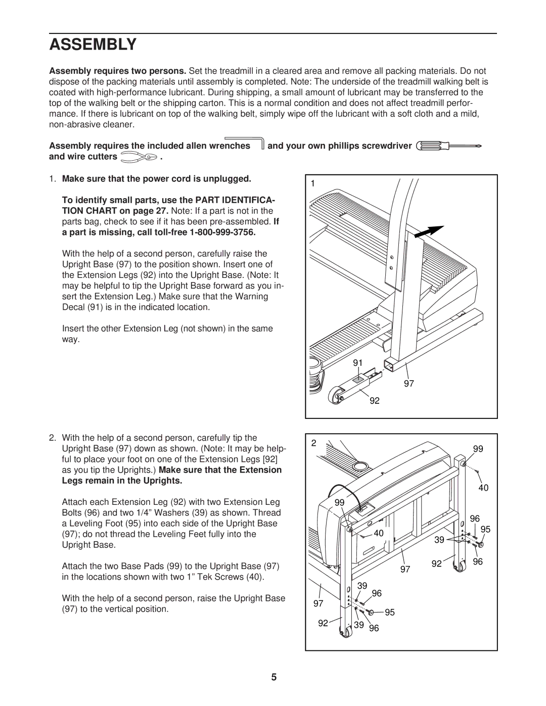
With the help of a second person, carefully raise the |
|
|
|
| ||
Upright Base (97) to the position shown. Insert one of |
|
|
|
| ||
the Extension Legs (92) into the Upright Base. (Note: It |
|
|
|
| ||
may be helpful to tip the Upright Base forward as you in- |
|
|
|
| ||
sert the Extension Leg.) Make sure that the Warning |
|
|
|
| ||
Decal (91) is in the indicated location. |
|
|
|
| ||
Insert the other Ext | ension Leg (not shown) in the same |
|
|
|
| |
way. |
|
|
|
|
|
|
|
|
|
| 91 |
|
|
|
|
|
| 97 |
|
|
|
|
|
| 92 |
|
|
2. With the help of a second person, carefully tip the | 2 |
|
|
| ||
Upright Base (97) down as shown. (Note: It may be help- |
|
| 99 | |||
|
|
| ||||
ful to place your foot on one of the Extension Legs [92] |
|
|
|
| ||
as you tip the Uprights.) | Make sure that the Extension |
|
|
|
| |
Legs remain in the Uprights. |
|
|
|
| 40 | |
|
|
|
|
|
| |
Attach each Extension Leg (92) with two Extension Leg |
| 99 |
|
| ||
Bolts (96) and two 1/4” Washers (39) as shown. Thread |
|
|
| 96 | ||
a Leveling Foot (95) into each side of the Upright Base |
|
|
| |||
| 40 |
| 95 | |||
(97); do not thread the Leveling Feet fully into the |
|
| ||||
| 39 |
| ||||
Upright Base. |
|
|
|
|
| |
|
|
|
|
|
| |
Attach the two Base Pads (99) to the Upright Base (97) |
| 97 | 92 | 96 | ||
in the locations shown with two 1” Tek Screws (40). |
|
|
| |||
| 39 |
|
| |||
|
|
|
|
|
| |
With the help of a second person, raise the Upright Base |
| 96 |
|
| ||
97 |
|
|
| |||
(97) to the vertical position. | 95 |
|
| |||
|
|
| ||||
|
|
|
|
|
| |
|
|
| 92 | 3996 |
|
|
|
|
| 5 |
|
|
|