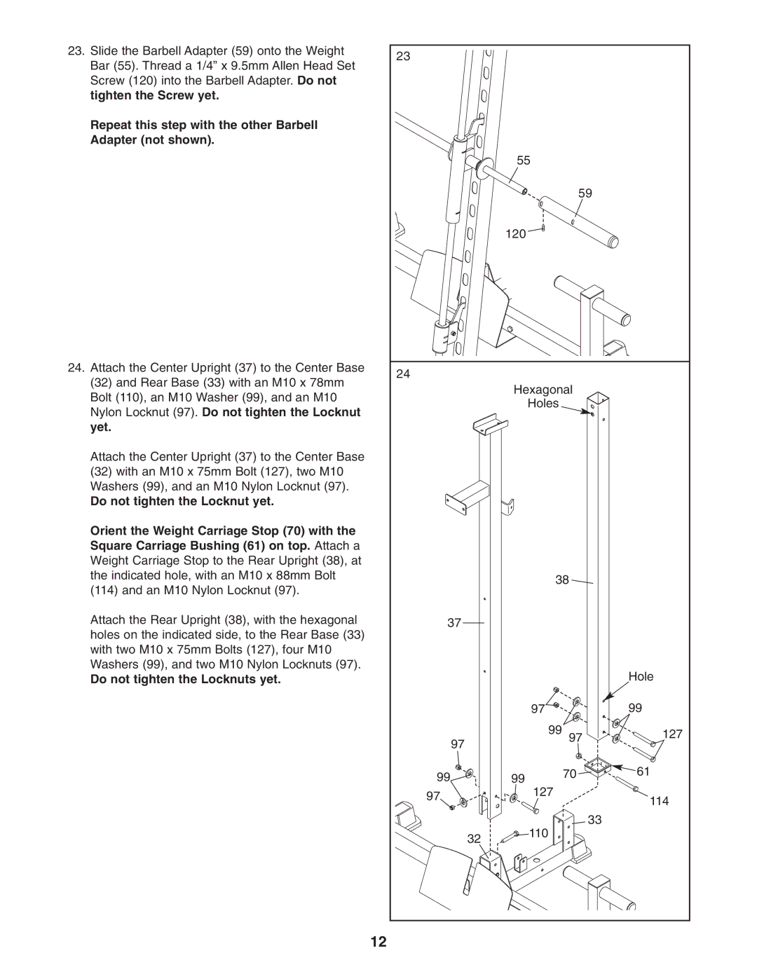
23. Slide the Barbell Adapter (59) onto the Weight | 23 |
|
|
|
|
Bar (55). Thread a 1/4” x 9.5mm Allen Head Set |
|
|
|
| |
|
|
|
|
| |
Screw (120) into the Barbell Adapter. Do not |
|
|
|
|
|
tighten the Screw yet. |
|
|
|
|
|
Repeat this step with the other Barbell |
|
|
|
|
|
Adapter (not shown). |
|
|
|
|
|
|
|
| 55 |
|
|
|
|
|
| 59 |
|
|
|
| 120 |
|
|
24. Attach the Center Upright (37) to the Center Base | 24 |
|
|
|
|
(32) and Rear Base (33) with an M10 x 78mm |
|
|
|
| |
|
| Hexagonal |
| ||
Bolt (110), an M10 Washer (99), and an M10 |
|
|
| ||
|
| Holes |
|
| |
Nylon Locknut (97). Do not tighten the Locknut |
|
|
|
| |
|
|
|
|
| |
yet. |
|
|
|
|
|
Attach the Center Upright (37) to the Center Base |
|
|
|
|
|
(32) with an M10 x 75mm Bolt (127), two M10 |
|
|
|
|
|
Washers (99), and an M10 Nylon Locknut (97). |
|
|
|
|
|
Do not tighten the Locknut yet. |
|
|
|
|
|
Orient the Weight Carriage Stop (70) with the |
|
|
|
|
|
Square Carriage Bushing (61) on top. Attach a |
|
|
|
|
|
Weight Carriage Stop to the Rear Upright (38), at |
|
|
|
|
|
the indicated hole, with an M10 x 88mm Bolt |
|
| 38 |
| |
(114) and an M10 Nylon Locknut (97). |
|
|
| ||
|
|
|
|
| |
Attach the Rear Upright (38), with the hexagonal | 37 |
|
|
|
|
holes on the indicated side, to the Rear Base (33) |
|
|
|
|
|
with two M10 x 75mm Bolts (127), four M10 |
|
|
|
|
|
Washers (99), and two M10 Nylon Locknuts (97). |
|
|
|
| Hole |
Do not tighten the Locknuts yet. |
|
|
|
| |
|
|
| 97 |
| 99 |
| 97 |
| 99 | 97 | 127 |
|
|
|
|
| |
| 99 |
| 99 | 70 | 61 |
| 97 |
| 127 |
| 114 |
|
|
|
| ||
|
|
|
|
| |
|
|
| 110 | 33 |
|
|
| 32 |
|
| |
|
|
|
|
| |
| 12 |
|
|
|
|
