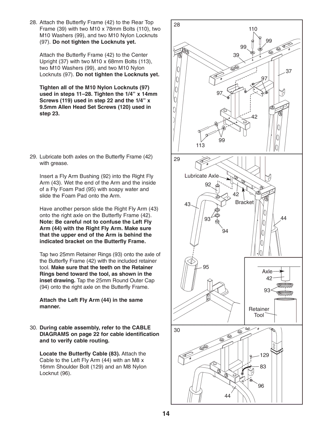
28. Attach the Butterfly Frame (42) to the Rear Top | 28 |
| |
Frame (39) with two M10 x 78mm Bolts (110), two | 110 | ||
| |||
M10 Washers (99), and two M10 Nylon Locknuts |
| 99 | |
(97). Do not tighten the Locknuts yet. |
| ||
|
| 99 | |
Attach the Butterfly Frame (42) to the Center |
| 39 | |
Upright (37) with two M10 x 68mm Bolts (113), |
|
| |
two M10 Washers (99), and two M10 Nylon |
| 37 | |
Locknuts (97). Do not tighten the Locknuts yet. |
| ||
| 97 | ||
|
| ||
Tighten all of the M10 Nylon Locknuts (97) | 97 |
| |
used in steps |
| ||
Screws (119) used in step 22 and the 1/4” x |
|
| |
9.5mm Allen Head Set Screws (120) used in |
|
| |
step 23. |
| 42 | |
|
| ||
| 99 |
| |
| 113 |
| |
29. Lubricate both axles on the Butterfly Frame (42) | 29 |
| |
with grease. |
| ||
|
| ||
Insert a Fly Arm Bushing (92) into the Right Fly | Lubricate Axle |
| |
Arm (43). Wet the end of the Arm and the inside | 92 |
| |
of a Fly Foam Pad (95) with soapy water and |
| ||
| 42 | ||
slide the Foam Pad onto the Arm. |
| ||
| 43 | Bracket | |
Have another person slide the Right Fly Arm (43) |
| ||
|
| ||
onto the right axle on the Butterfly Frame (42). | 93 | 44 | |
Note: Be careful not to confuse the Left Fly | |||
|
| ||
Arm (44) with the Right Fly Arm. Make sure | 94 |
| |
that the upper end of the Arm is behind the |
| ||
|
| ||
indicated bracket on the Butterfly Frame. |
|
| |
Tap two 25mm Retainer Rings (93) onto the axle of |
|
| |
the Butterfly Frame (42) with the included retainer | 95 |
| |
tool. Make sure that the teeth on the Retainer | Axle | ||
Rings bend toward the tool, as shown in the |
| ||
| 42 | ||
inset drawing. Tap the 25mm Round Outer Cap |
| ||
|
| ||
(94) onto the right axle on the Butterfly Frame. |
| 93 | |
|
| ||
Attach the Left Fly Arm (44) in the same |
|
| |
manner. |
| Retainer | |
|
| ||
|
| Tool | |
30. During cable assembly, refer to the CABLE | 30 |
| |
DIAGRAMS on page 22 for cable identification |
| ||
|
| ||
and to verify cable routing. |
|
| |
Locate the Butterfly Cable (83). Attach the |
| 129 | |
Cable to the Left Fly Arm (44) with an M8 x |
|
| |
16mm Shoulder Bolt (129) and an M8 Nylon |
| 83 | |
Locknut (96). |
|
| |
|
| 96 | |
| 44 |
| |
| 14 |
|