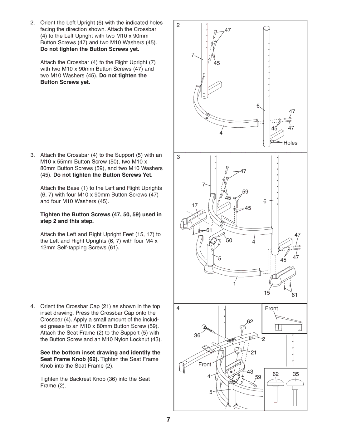
2.Orient the Left Upright (6) with the indicated holes facing the direction shown. Attach the Crossbar
(4) to the Left Upright with two M10 x 90mm Button Screws (47) and two M10 Washers (45).
Do not tighten the Button Screws yet.
Attach the Crossbar (4) to the Right Upright (7) with two M10 x 90mm Button Screws (47) and two M10 Washers (45). Do not tighten the
Button Screws yet.
3.Attach the Crossbar (4) to the Support (5) with an M10 x 55mm Button Screw (50), two M10 x 80mm Button Screws (59), and two M10 Washers (45). Do not tighten the Button Screws Yet.
Attach the Base (1) to the Left and Right Uprights (6, 7) with four M10 x 90mm Button Screws (47) and four M10 Washers (45).
Tighten the Button Screws (47, 50, 59) used in step 2 and this step.
Attach the Left and Right Upright Feet (15, 17) to the Left and Right Uprights (6, 7) with four M4 x 12mm
4.Orient the Crossbar Cap (21) as shown in the top inset drawing. Press the Crossbar Cap onto the Crossbar (4). Apply a small amount of the includ- ed grease to an M10 x 80mm Button Screw (59). Attach the Seat Frame (2) to the Support (5) with the Button Screw and an M10 Nylon Locknut (43).
See the bottom inset drawing and identify the Seat Frame Knob (62). Tighten the Seat Frame Knob into the Seat Frame (2).
Tighten the Backrest Knob (36) into the Seat Frame (2).
7
2 |
|
|
| |
47 |
|
|
| |
7 |
|
|
| |
45 |
|
|
| |
| 6 |
| 47 | |
|
|
| ||
4 |
| 45 | 47 | |
|
|
| ||
|
| Holes | ||
3 |
|
|
| |
| 47 |
|
| |
7 |
|
|
| |
45 | 59 |
|
| |
| 6 |
| ||
17 |
|
| ||
45 |
|
| ||
|
|
| ||
61 |
|
| 47 | |
50 |
|
| ||
4 |
|
| ||
5 |
| 45 | 47 | |
| 1 |
|
| |
|
| 15 | 61 | |
|
|
| ||
4 |
| Front |
| |
| 62 |
|
| |
36 |
| 2 |
| |
|
|
| ||
| 21 |
|
| |
Front |
|
|
| |
4 | 43 | 62 | 35 | |
59 | ||||
|
| |||
5 |
| Frame Knob (62) |
| |
|
| Seat |
| |
|
|
| Curl Knob (35) | |