ASSEMBLY
Before beginning assembly, carefully read the following information and instructions:
¥Place all parts of the weight bench in a cleared area and remove the packing materials; do not dispose of the packing materials until assembly is completed.
¥For help identifying the small parts used in assembly, use the PART IDENTIFICATION CHART located in the center of this manual. Note: Some small parts may have been pre- attached for shipping. If a part is not in the parts bag, check to see if it has been
¥As you assemble the weight bench, be sure that all parts are oriented as shown in the drawings.
¥Tighten all parts as you assemble them, unless instructed to do otherwise.
THE FOLLOWING TOOLS (NOT INCLUDED) ARE REQUIRED FOR ASSEMBLY:
¥Two (2) adjustable wrenches ![]()
¥One (1) standard screwdriver ![]()
¥One (1) phillips screwdriver ![]()
¥One (1) rubber mallet ![]()
¥Lubricant, such as grease or petroleum jelly, and soapy water will also be needed.
Assembly will be more convenient if you have the following tools: A socket set, a set of
1. Before beginning assembly, be sure that you | 1 |
|
|
|
| |
have read and understand the information in |
|
|
|
| ||
|
|
|
|
| ||
the box above. | 24 |
|
| 14 |
| |
|
|
|
|
| ||
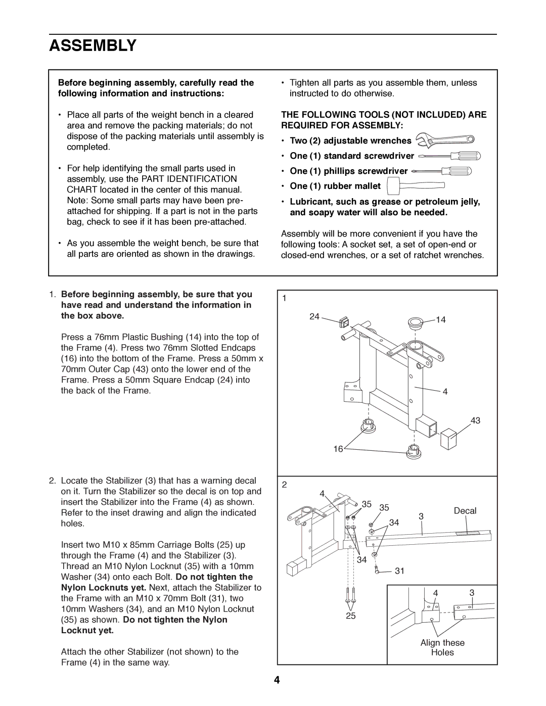
Press a 76mm Plastic Bushing (14) into the top of |
|
|
|
|
| |
the Frame (4). Press two 76mm Slotted Endcaps |
|
|
|
|
| |
(16) into the bottom of the Frame. Press a 50mm x |
|
|
|
|
| |
70mm Outer Cap (43) onto the lower end of the |
|
|
|
|
| |
Frame. Press a 50mm Square Endcap (24) into |
|
|
|
|
| |
the back of the Frame. |
|
|
| 4 |
| |
|
|
|
|
| 43 | |
| 16 |
|
|
|
| |
2. Locate the Stabilizer (3) that has a warning decal | 2 |
|
|
|
| |
on it. Turn the Stabilizer so the decal is on top and |
|
|
|
| ||
4 |
|
|
|
| ||
insert the Stabilizer into the Frame (4) as shown. | 35 | 35 |
| Decal | ||
Refer to the inset drawing and align the indicated | 3 | |||||
| 34 | |||||
holes. |
|
|
| |||
|
|
|
| |||
Insert two M10 x 85mm Carriage Bolts (25) up |
|
|
|
|
| |
through the Frame (4) and the Stabilizer (3). | 34 |
|
|
|
| |
Thread an M10 Nylon Locknut (35) with a 10mm |
|
|
|
| ||
| 31 |
|
|
| ||
Washer (34) onto each Bolt. Do not tighten the |
|
|
|
| ||
|
|
|
|
| ||
Nylon Locknuts yet. Next, attach the Stabilizer to |
|
|
| 4 | 3 | |
the Frame with an M10 x 70mm Bolt (31), two |
|
|
| |||
|
|
|
|
| ||
10mm Washers (34), and an M10 Nylon Locknut | 25 |
|
|
|
| |
(35) as shown. Do not tighten the Nylon |
|
|
|
| ||
|
|
|
|
| ||
Locknut yet. |
|
|
|
|
| |
Attach the other Stabilizer (not shown) to the |
|
| Align these |
| ||
|
|
| Holes |
| ||
Frame (4) in the same way. |
|
|
|
|
| |
| 4 |
|
|
|
| |