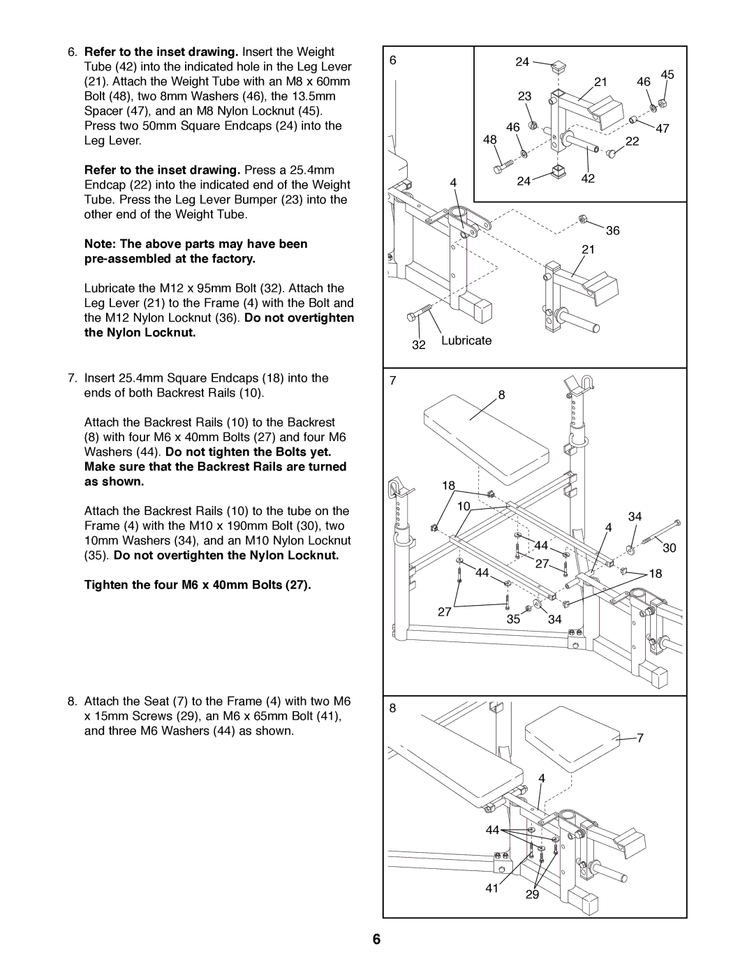
6. Refer to the inset drawing. Insert the Weight | 6 |
|
| 24 |
|
|
|
Tube (42) into the indicated hole in the Leg Lever |
|
|
|
| 45 | ||
|
|
|
|
|
| ||
(21). Attach the Weight Tube with an M8 x 60mm |
|
|
|
| 21 | 46 | |
Bolt (48), two 8mm Washers (46), the 13.5mm |
|
|
| 23 |
|
|
|
Spacer (47), and an M8 Nylon Locknut (45). |
|
|
|
|
|
|
|
Press two 50mm Square Endcaps (24) into the |
| 48 |
| 46 |
|
| 47 |
Leg Lever. |
|
|
|
| 22 |
| |
Refer to the inset drawing. Press a 25.4mm |
| 4 |
| 24 | 42 |
|
|
Endcap (22) into the indicated end of the Weight |
|
|
|
| |||
Tube. Press the Leg Lever Bumper (23) into the |
|
|
|
|
|
|
|
other end of the Weight Tube. |
|
|
|
|
|
|
|
Note: The above parts may have been |
|
|
|
| 36 |
|
|
|
|
|
| 21 |
|
| |
|
|
|
|
|
|
| |
|
|
|
|
|
|
| |
Lubricate the M12 x 95mm Bolt (32). Attach the |
|
|
|
|
|
|
|
Leg Lever (21) to the Frame (4) with the Bolt and |
|
|
|
|
|
|
|
the M12 Nylon Locknut (36). Do not overtighten |
|
|
|
|
|
|
|
the Nylon Locknut. | 32 | Lubricate |
|
|
|
|
|
|
|
|
|
|
| ||
|
|
|
|
|
|
| |
7. Insert 25.4mm Square Endcaps (18) into the | 7 |
|
|
|
|
|
|
ends of both Backrest Rails (10). |
|
| 8 |
|
|
|
|
Attach the Backrest Rails (10) to the Backrest |
|
|
|
|
|
|
|
(8) with four M6 x 40mm Bolts (27) and four M6 |
|
|
|
|
|
|
|
Washers (44). Do not tighten the Bolts yet. |
|
|
|
|
|
|
|
Make sure that the Backrest Rails are turned |
|
|
|
|
|
|
|
as shown. |
| 18 |
|
|
|
|
|
|
|
|
|
|
|
| |
Attach the Backrest Rails (10) to the tube on the |
| 10 |
|
|
| 34 |
|
|
|
|
|
|
| ||
Frame (4) with the M10 x 190mm Bolt (30), two |
|
|
|
| 4 |
| |
|
|
|
|
|
| ||
10mm Washers (34), and an M10 Nylon Locknut |
|
|
| 44 |
|
| 30 |
(35). Do not overtighten the Nylon Locknut. |
|
|
|
|
| ||
|
|
| 27 |
|
| ||
|
| 44 |
| 18 | |||
Tighten the four M6 x 40mm Bolts (27). |
|
|
|
| |||
|
|
|
|
|
|
| |
|
| 27 |
| 35 | 34 |
|
|
|
|
|
|
|
| ||
8. Attach the Seat (7) to the Frame (4) with two M6 | 8 |
|
|
|
|
|
|
x 15mm Screws (29), an M6 x 65mm Bolt (41), |
|
|
|
|
|
| |
|
|
|
|
|
|
| |
and three M6 Washers (44) as shown. |
|
|
|
|
| 7 |
|
|
|
|
|
|
|
| |
|
|
|
| 4 |
|
|
|
|
| 44 |
|
|
|
| |
|
| 41 | 29 |
|
|
| |
|
|
|
|
|
|
| |
| 6 |
|
|
|
|
|
|
