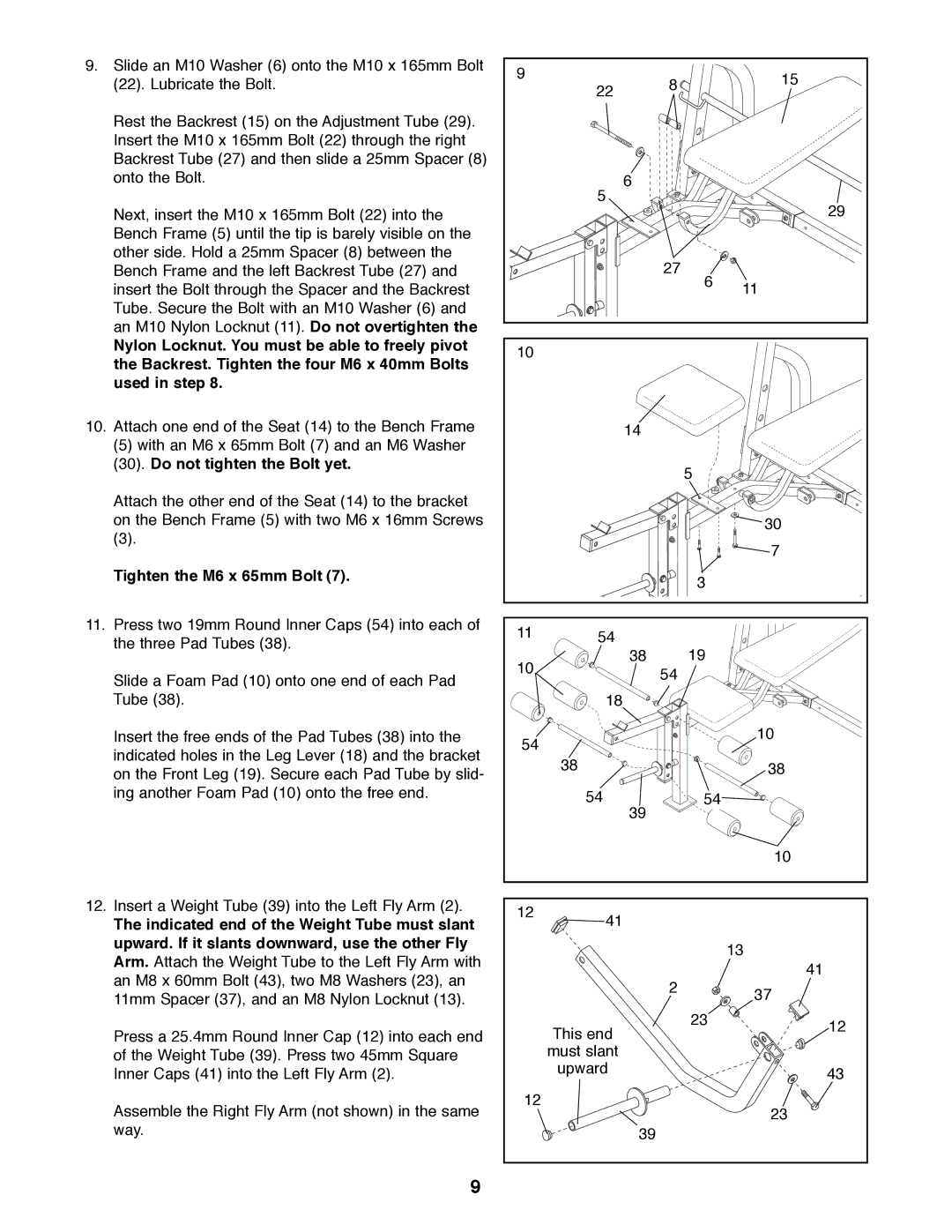
9.Slide an M10 Washer (6) onto the M10 x 165mm Bolt
(22).Lubricate the Bolt.
Rest the Backrest (15) on the Adjustment Tube (29). Insert the M10 x 165mm Bolt (22) through the right Backrest Tube (27) and then slide a 25mm Spacer (8) onto the Bolt.
Next, insert the M10 x 165mm Bolt (22) into the Bench Frame (5) until the tip is barely visible on the other side. Hold a 25mm Spacer (8) between the Bench Frame and the left Backrest Tube (27) and insert the Bolt through the Spacer and the Backrest Tube. Secure the Bolt with an M10 Washer (6) and an M10 Nylon Locknut (11). Do not overtighten the
Nylon Locknut. You must be able to freely pivot the Backrest. Tighten the four M6 x 40mm Bolts used in step 8.
10.Attach one end of the Seat (14) to the Bench Frame
(5)with an M6 x 65mm Bolt (7) and an M6 Washer
(30).Do not tighten the Bolt yet.
Attach the other end of the Seat (14) to the bracket on the Bench Frame (5) with two M6 x 16mm Screws
(3).
Tighten the M6 x 65mm Bolt (7).
11.Press two 19mm Round Inner Caps (54) into each of the three Pad Tubes (38).
Slide a Foam Pad (10) onto one end of each Pad Tube (38).
Insert the free ends of the Pad Tubes (38) into the indicated holes in the Leg Lever (18) and the bracket on the Front Leg (19). Secure each Pad Tube by slid- ing another Foam Pad (10) onto the free end.
12.Insert a Weight Tube (39) into the Left Fly Arm (2).
The indicated end of the Weight Tube must slant upward. If it slants downward, use the other Fly Arm. Attach the Weight Tube to the Left Fly Arm with an M8 x 60mm Bolt (43), two M8 Washers (23), an 11mm Spacer (37), and an M8 Nylon Locknut (13).
Press a 25.4mm Round Inner Cap (12) into each end of the Weight Tube (39). Press two 45mm Square Inner Caps (41) into the Left Fly Arm (2).
Assemble the Right Fly Arm (not shown) in the same way.
9 |
| 8 |
| 15 |
| 22 |
| ||
|
|
| ||
|
|
|
| |
| 6 |
|
|
|
| 5 |
|
| 29 |
|
|
|
| |
|
| 27 | 6 |
|
|
|
| 11 | |
|
|
|
| |
10 |
|
|
|
|
| 14 |
|
|
|
|
|
| 5 |
|
|
|
|
| 30 |
|
|
|
| 7 |
|
|
| 3 |
|
11 | 54 |
|
|
|
10 | 38 |
| 19 |
|
| 54 |
|
| |
|
|
|
| |
| 18 |
|
|
|
54 |
|
|
| 10 |
|
|
|
| |
| 38 |
|
| 38 |
| 54 |
| 54 |
|
| 39 |
|
|
|
|
|
|
| 10 |
12 | 41 |
|
|
|
|
|
|
| |
|
|
|
| 13 |
|
|
|
| 41 |
|
| 2 |
| 37 |
|
|
|
| |
| This end |
| 23 | 12 |
|
|
| ||
|
|
|
| |
| must slant |
|
|
|
| upward |
|
| 43 |
|
|
|
| |
12 |
|
|
| 23 |
|
|
|
| |
| 39 |
|
|
|
9