PART IDENTIFICATION CHART
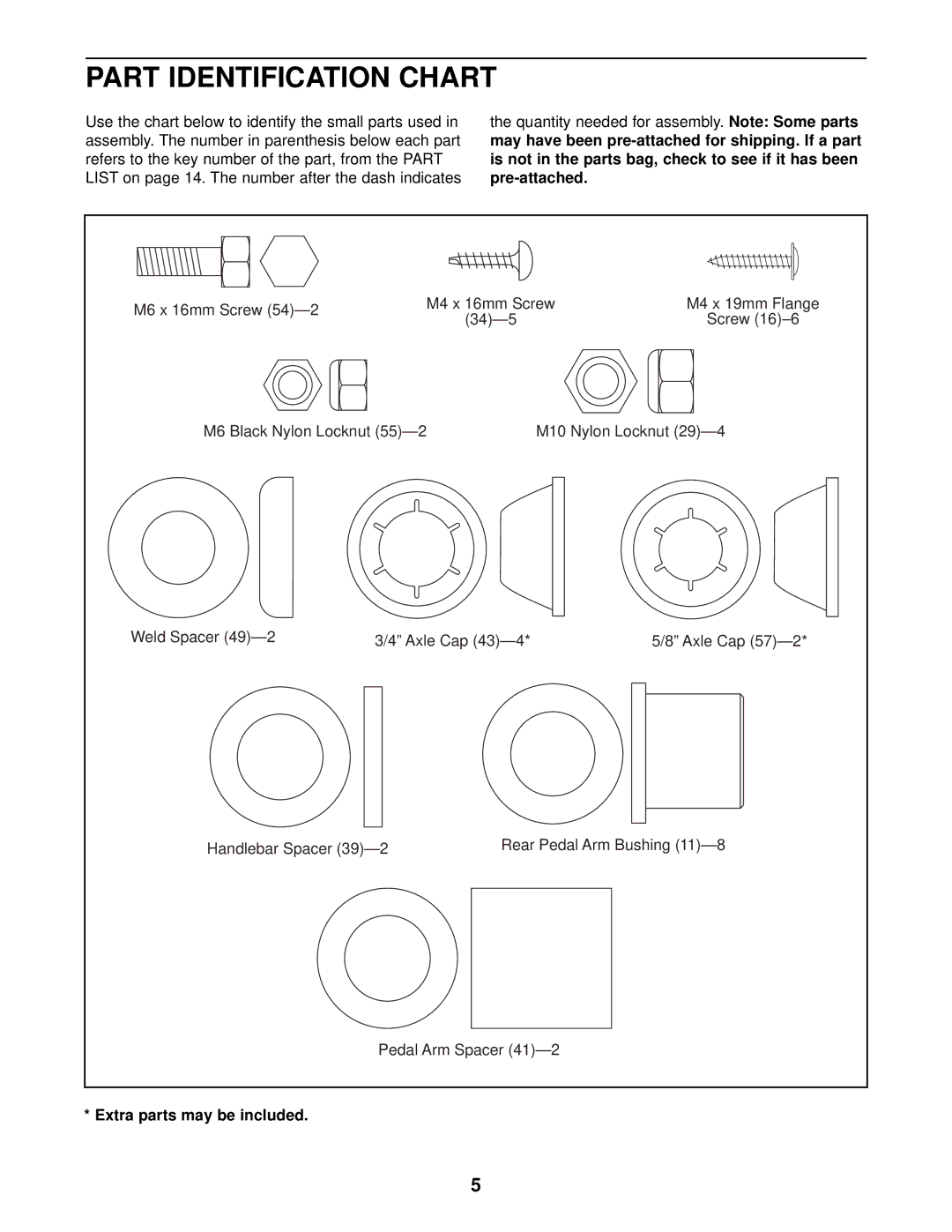
Use the chart below to identify the small parts used in assembly. The number in parenthesis below each part refers to the key number of the part, from the PART LIST on page 14. The number after the dash indicates
the quantity needed for assembly. Note: Some parts may have been
M6 x 16mm Screw | M4 x 16mm Screw | M4 x 19mm Flange | |
Screw | |||
|
M6 Black Nylon Locknut | M10 Nylon Locknut |
Weld Spacer | 3/4” Axle Cap | 5/8” Axle Cap |
Handlebar Spacer | Rear Pedal Arm Bushing |
Pedal Arm Spacer
* Extra parts may be included.
5
