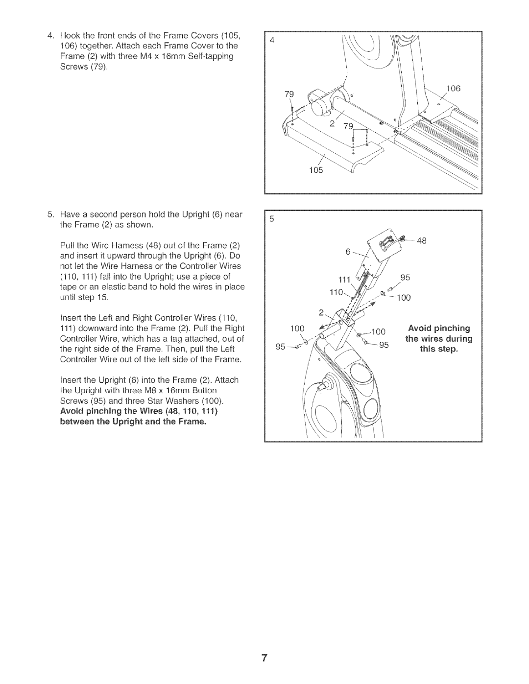
4. Hook the front ends of the Frame Covers (105, | 4 |
106)together. Attach each Frame Cover to the Frame (2) with three M4 x 16mm
79
106
Have a second person hoJd the Upright (6) near the Frame (2) as shown.
Puff the Wire Harness (48) out of the Frame (2)
and insert it upward through the Upright (6). Do not let the Wire Harness or the ControJJer Wires
(110, 111) falJ into the Upright; use a piece of tape or an eJastic band to hoJd the wires in place untiJ step 15.
Insert the Left and Right ControJJerWires (110,
111)downward into the Frame (2). Puff the Right Controller Wire, which has a tag attached, out of
the right side of the Frame. Then, pulJ the Left ControJJer Wire out of the left side of the Frame.
Insert the Upright (6) into the Frame (2). Attach the Upright with three M8 x 16mm Button Screws (95) and three Star Washers (100). Avoid pinching the Wires (48, 110, 111) between the Upright and the Frame.
105
111
11
IO0 | Avoid | pinching |
'\ | the wires during | |
| ||
| this | step. |
7