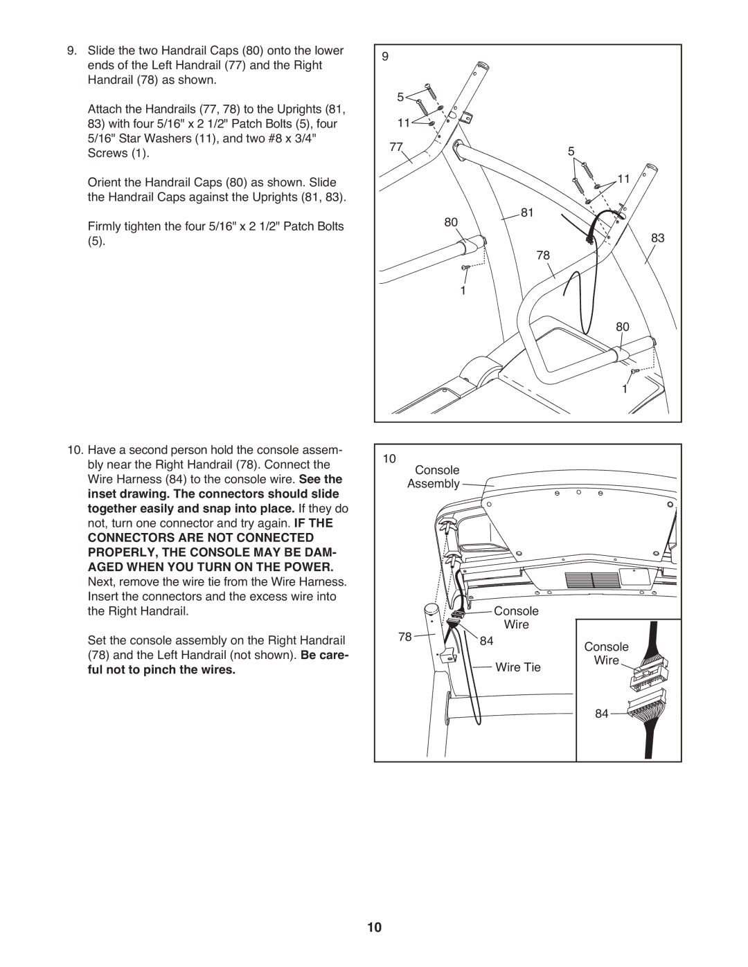
9. Slide the two Handrail Caps (80) onto the lower | 9 |
|
|
ends of the Left Handrail (77) and the Right |
|
| |
Handrail (78) as shown. | 5 |
|
|
Attach the Handrails (77, 78) to the Uprights (81, |
|
| |
83) with four 5/16" x 2 1/2" Patch Bolts (5), four | 11 |
|
|
5/16" Star Washers (11), and two #8 x 3/4" | 77 |
| 5 |
Screws (1). |
| ||
Orient the Handrail Caps (80) as shown. Slide |
|
| 11 |
the Handrail Caps against the Uprights (81, 83). | 80 | 81 |
|
Firmly tighten the four 5/16" x 2 1/2" Patch Bolts | 83 | ||
(5). |
| 78 | |
|
|
| |
|
| 1 | 80 |
|
|
| |
|
|
| 1 |
10. Have a second person hold the console assem- | 10 |
|
|
|
|
bly near the Right Handrail (78). Connect the | Console |
|
|
| |
Wire Harness (84) to the console wire. See the |
|
|
|
| |
inset drawing. The connectors should slide |
| Assembly |
|
|
|
together easily and snap into place. If they do |
|
|
|
|
|
not, turn one connector and try again. IF THE |
|
|
|
|
|
CONNECTORS ARE NOT CONNECTED |
|
|
|
|
|
PROPERLY, THE CONSOLE MAY BE DAM- |
|
|
|
|
|
AGED WHEN YOU TURN ON THE POWER. |
|
|
|
|
|
Next, remove the wire tie from the Wire Harness. |
|
|
|
|
|
Insert the connectors and the excess wire into |
|
|
| Console |
|
the Right Handrail. |
| 78 | 84 |
| |
Set the console assembly on the Right Handrail |
| Wire | Console | ||
(78) and the Left Handrail (not shown). Be care- |
|
|
| Wire Tie | |
ful not to pinch the wires. |
|
|
| Wire | |
|
|
|
|
| 84 |
10