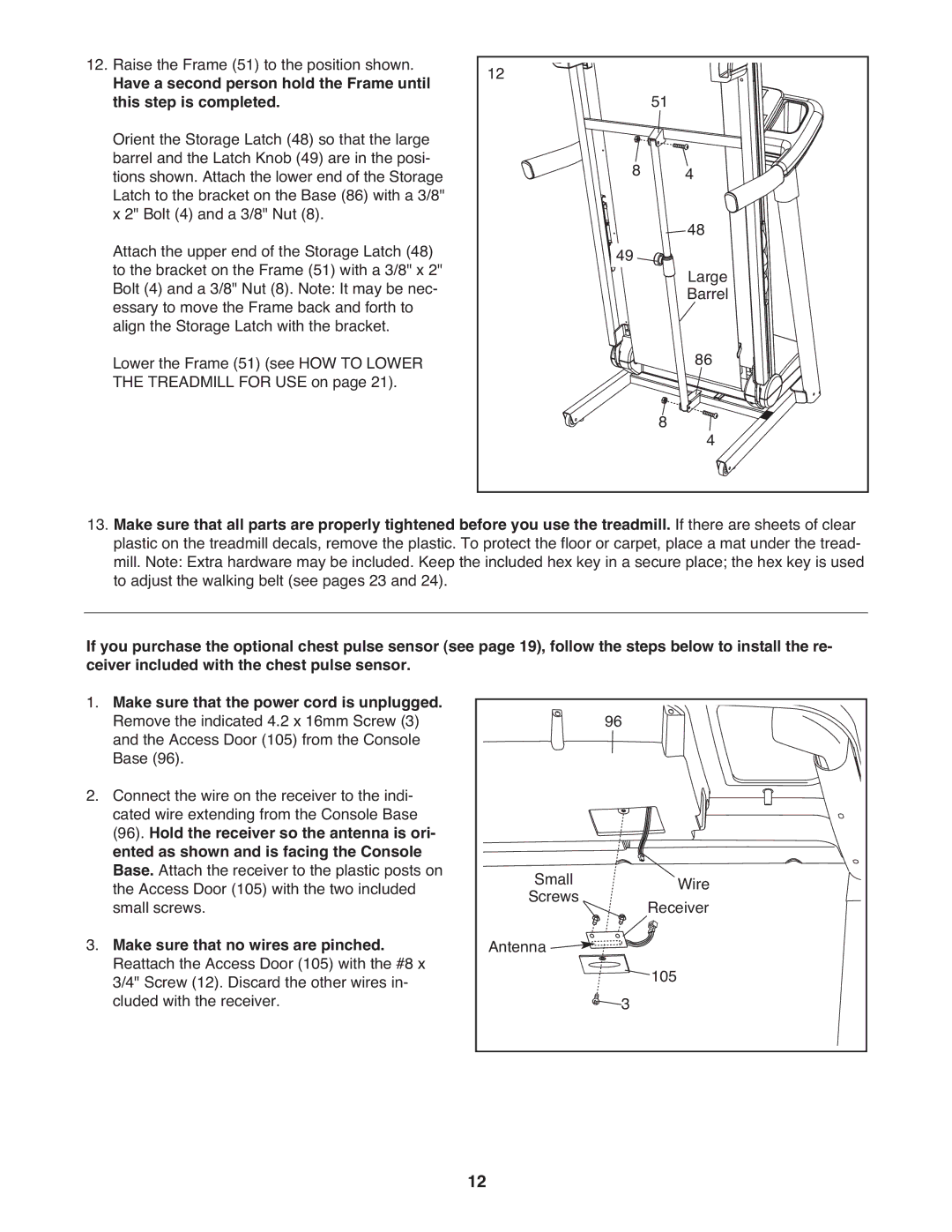
12. Raise the Frame (51) to the position shown. | 12 |
|
|
Have a second person hold the Frame until | 51 |
| |
this step is completed. |
|
| |
Orient the Storage Latch (48) so that the large |
|
|
|
barrel and the Latch Knob (49) are in the posi- | 8 |
| 4 |
tions shown. Attach the lower end of the Storage |
| ||
Latch to the bracket on the Base (86) with a 3/8" |
|
|
|
x 2" Bolt (4) and a 3/8" Nut (8). |
|
| 48 |
Attach the upper end of the Storage Latch (48) | 49 |
| |
|
| ||
to the bracket on the Frame (51) with a 3/8" x 2" |
|
| Large |
Bolt (4) and a 3/8" Nut (8). Note: It may be nec- |
|
| |
essary to move the Frame back and forth to |
|
| Barrel |
align the Storage Latch with the bracket. |
|
| 86 |
Lower the Frame (51) (see HOW TO LOWER |
|
| |
THE TREADMILL FOR USE on page 21). |
| 8 |
|
|
| 4 | |
|
|
|
13.Make sure that all parts are properly tightened before you use the treadmill. If there are sheets of clear plastic on the treadmill decals, remove the plastic. To protect the floor or carpet, place a mat under the tread- mill. Note: Extra hardware may be included. Keep the included hex key in a secure place; the hex key is used to adjust the walking belt (see pages 23 and 24).
If you purchase the optional chest pulse sensor (see page 19), follow the steps below to install the re- ceiver included with the chest pulse sensor.
1. Make sure that the power cord is unplugged. |
| 96 |
|
Remove the indicated 4.2 x 16mm Screw (3) |
|
| |
and the Access Door (105) from the Console |
|
|
|
Base (96). |
|
|
|
2. Connect the wire on the receiver to the indi- |
|
|
|
cated wire extending from the Console Base |
|
|
|
(96). Hold the receiver so the antenna is ori- |
|
|
|
ented as shown and is facing the Console |
|
|
|
Base. Attach the receiver to the plastic posts on | Small |
| Wire |
the Access Door (105) with the two included |
| ||
small screws. | Screws |
| Receiver |
3. Make sure that no wires are pinched. | Antenna |
|
|
Reattach the Access Door (105) with the #8 x |
|
| 105 |
3/4" Screw (12). Discard the other wires in- |
| 3 | |
cluded with the receiver. |
|
|
12