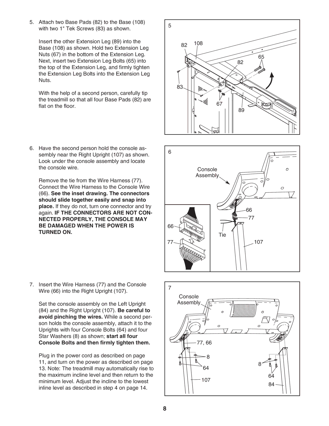
5. Attach two Base Pads (82) to the Base (108) | 5 |
|
|
with two 1" Tek Screws (83) as shown. |
|
| |
|
|
| |
Insert the other Extension Leg (89) into the |
| 82 | 108 |
Base (108) as shown. Hold two Extension Leg |
| ||
|
| ||
|
|
| |
Nuts (67) in the bottom of the Extension Leg. |
|
| 65 |
Next, insert two Extension Leg Bolts (65) into |
|
| |
|
| 82 | |
the top of the Extension Leg, and firmly tighten |
|
|
|
the Extension Leg Bolts into the Extension Leg |
|
|
|
Nuts. |
|
|
|
With the help of a second person, carefully tip |
| 83 |
|
|
|
| |
the treadmill so that all four Base Pads (82) are |
|
| 67 |
flat on the floor. |
|
| |
|
| 89 | |
|
|
| |
6. Have the second person hold the console as- | 6 |
|
|
sembly near the Right Upright (107) as shown. |
|
| |
|
|
| |
Look under the console assembly and locate |
|
|
|
the console wire. |
|
| Console |
|
|
| |
Remove the tie from the Wire Harness (77). |
|
| Assembly |
|
|
| |
Connect the Wire Harness to the Console Wire |
|
|
|
(66). See the inset drawing. The connectors |
|
|
|
should slide together easily and snap into |
|
|
|
place. If they do not, turn one connector and try |
|
| 66 |
again. IF THE CONNECTORS ARE NOT CON- |
|
| |
|
| 77 | |
NECTED PROPERLY, THE CONSOLE MAY |
|
| |
BE DAMAGED WHEN THE POWER IS | 66 |
|
|
TURNED ON. |
|
| Tie |
|
|
| |
| 77 |
| 107 |
7. Insert the Wire Harness (77) and the Console | 7 |
|
|
Wire (66) into the Right Upright (107). |
|
| |
| Console | ||
|
| ||
Set the console assembly on the Left Upright |
| Assembly | |
(84) and the Right Upright (107). Be careful to |
|
|
|
avoid pinching the wires. While a second per- |
|
|
|
son holds the console assembly, attach it to the |
|
|
|
Uprights with four Console Bolts (64) and four |
|
|
|
Star Washers (8) as shown; start all four |
|
|
|
Console Bolts and then firmly tighten them. |
|
| 77, 66 |
Plug in the power cord as described on page |
|
| 8 |
11, and turn on the power as described on page |
|
| 8 |
13. Note: The treadmill may automatically rise to |
|
| |
|
| 64 | |
the maximum incline level and then return to the |
|
| 64 |
minimum level. Adjust the incline to the lowest |
|
| 107 |
inline level as described in step 4 on page 14. |
|
| 84 |
|
|
| |
| 8 |
|
|