Electrical System Connections
Connection to +24V, +36V and +48V Systems
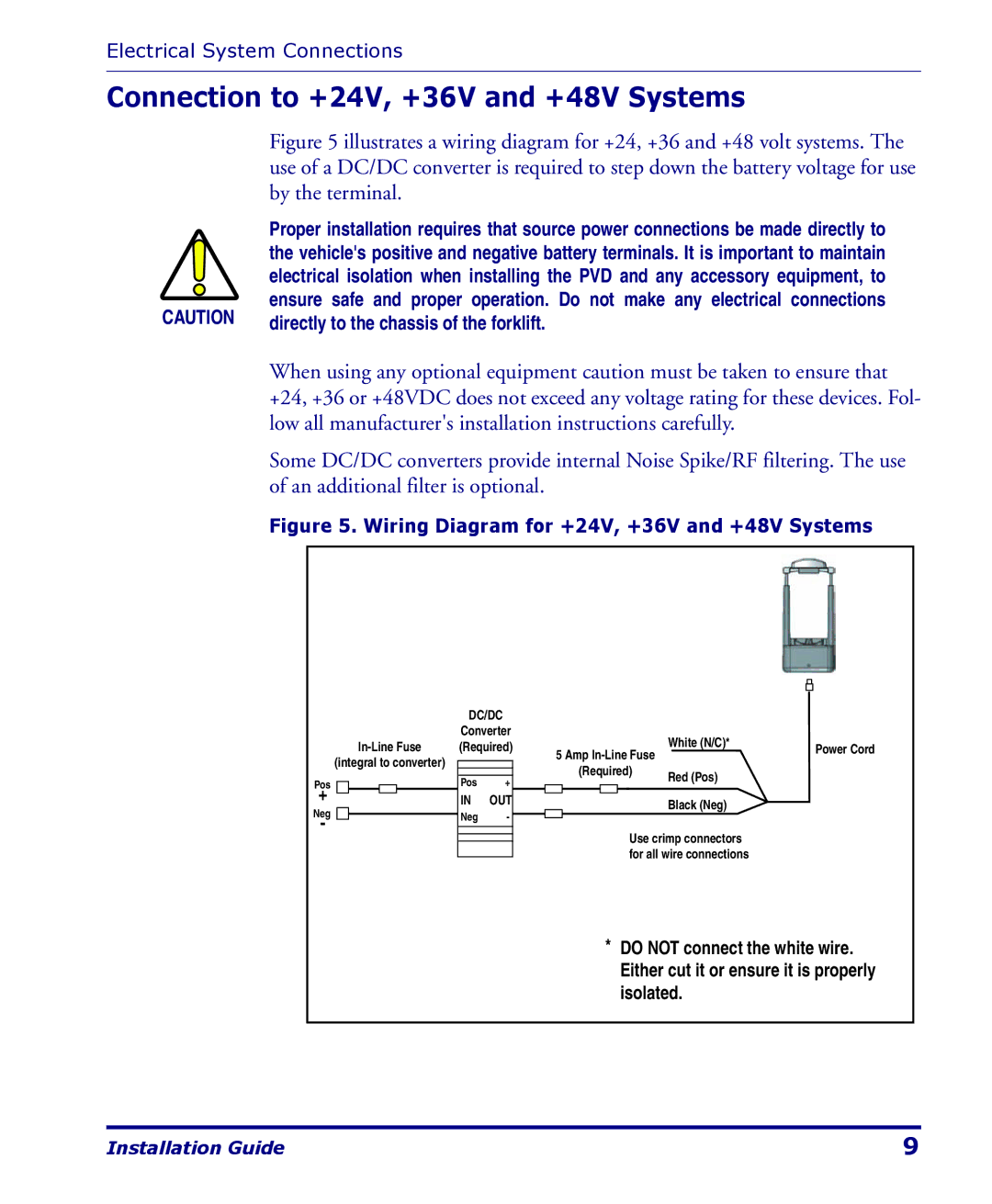
Figure 5 illustrates a wiring diagram for +24, +36 and +48 volt systems. The use of a DC/DC converter is required to step down the battery voltage for use by the terminal.
| Proper installation requires that source power connections be made directly to | |
| the vehicle's positive and negative battery terminals. It is important to maintain | |
| electrical isolation when installing the PVD and any accessory equipment, to | |
CAUTION | ensure safe and proper operation. Do not make any electrical connections | |
directly to the chassis of the forklift. | ||
|
When using any optional equipment caution must be taken to ensure that +24, +36 or +48VDC does not exceed any voltage rating for these devices. Fol- low all manufacturer's installation instructions carefully.
Some DC/DC converters provide internal Noise Spike/RF filtering. The use of an additional filter is optional.
Figure 5. Wiring Diagram for +24V, +36V and +48V Systems
(integral to converter)
Pos
+
Neg
-
DC/DC
Converter (Required)
Pos +
IN OUT
Neg -
5 Amp | White (N/C)* | Power Cord | ||||||||
| ||||||||||
|
| |||||||||
|
| (Required) | Red (Pos) |
| ||||||
|
|
|
|
|
|
|
|
|
| |
|
|
|
|
|
|
|
|
| Black (Neg) |
|
|
|
|
|
|
|
| Use crimp connectors |
| ||
|
|
|
|
|
|
| for all wire connections |
| ||
*DO NOT connect the white wire. Either cut it or ensure it is properly isolated.
Installation Guide | 9 |