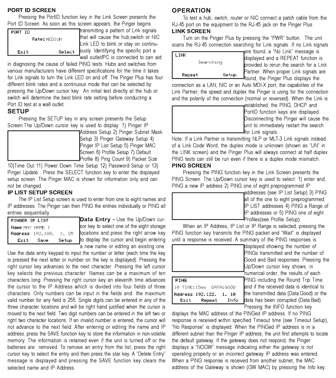
PORT ID SCREEN
Pressing the PortID function key in the Link Screen presents the Port ID Screen. As soon as this screen appears, the Pinger begins
transmitting a pattern of Link signals that will cause the hub,switch or NIC Link LED to blink or stay on continu- ously. Identifying the specific port a wall outlet/PC is connected to can aid
in diagnosing the cause of failed PING tests. Hubs and switches from various manufacturers have different specifications for the time it takes for Link signals to turn the Link LED on and off. The Pinger Plus has four different blink rates and a continuous mode that can be selected by pressing the Up/Down cursor key. An initial test directly at the hub or switch will determine the best blink rate setting before conducting a Port ID test at a wall outlet.
SETUP
Pressing the SETUP key in any screen presents the Setup Screen.The Up/Down cursor key is used to display: 1) Pinger IP
Address Setup 2) Pinger Subnet Mask Setup 3) Pinger Gateway Setup 4) Pinger IP List Setup 5) Pinger MAC Screen 6) Profile Setup 7) Default Profile 8) Ping Count 9) Packet Size
10)Time Out 11) Power Down Time Setup 12) Password Setup or 13) Pinger Update . Press the SELECT function key to enter the displayed setup screen. The Pinger MAC is shown for information only and can not be changed.
IP LIST SETUP SCREEN
The IP List Setup screen is used to enter from one to eight names and IP addresses. The Pinger can then PING the entries individually or PING all entries sequentially.
Data Entry - Use the Up/Down cur- sor key to select one of the eight storage locations and press the right arrow key to display the cursor and begin entering a new name or editing an existing one.
Use the data entry keypad to input the number or letter (each time the key is pressed the next letter or number on the key is displayed). Pressing the right cursor key advances to the next character. Pressing the left cursor key selects the previous character. Names can be a maximum of ten characters long. Pressing the right cursor key an eleventh time advances the cursor to the IP Address which is divided into four fields of three characters. Only numbers can be input in the fields and the maximum valid number for any field is 255. Single digits can be entered in any of the three character locations and will be right hand justified when the cursor is moved to the next field. Two digit numbers can be entered in the left two or right two character locations. If an invalid number is entered, the cursor will not advance to the next field. After entering or editing the name and IP address, press the SAVE function key to store the information in
OPERATION
To test a hub, switch, router or NIC connect a patch cable from the
LINK SCREEN
Turn on the Pinger Plus by pressing the “PWR” button. The unit scans the
are found, a “No Link” message is displayed and a REPEAT function is provided to rerun the search for a Link Partner. When proper Link signals are found, the Pinger Plus displays the
connection as a LAN, NIC or an Auto
established, the PING, DHCP and PortID function keys are displayed. Disconnecting the Pinger will cause the unit to immediately restart the search for Link signals.
Note: If a Link Partner is transmitting NLP or
PING SCREEN
Pressing the PING function key in the Link Screen presents the PING Screen. The Up/Down cursor key is used to select: 1) enter and PING a new IP address 2) PING one of eight preprogrammed IP
addresses (see IP List Setup) 3) PING all of the one to eight preprogrammed IP LIST addresses 4) PING a Range of IP addresses or 5) PING one of eight Profiles(see Profile Setup).
When an IP Address, IP List or IP Range is selected, pressing the PING function key transmits the PING packet and “Wait” is displayed until a response is received. A summary of the PING responses is
displayed showing the number of PINGs transmitted and the number of Good and Bad responses. Pressing the Up/Down cursor key shows, in numerical order, the results of each PING including the Round Trip Time and if the received data is identical to the transmitted data (Data:Good) or the data has been corrupted (Data:Bad). Pressing the INFO function key
displays the MAC address of the PINGed IP address. If no PING response is received within specified Timeout time (see Timeout Setup), “No Response” is displayed. When the PINGed IP address is in a different subnet than the Pinger IP address, the unit first attempts to locate the default gateway. If the gateway does not respond, the Pinger displays a “NOGW” message indicating either the gateway is not operating properly or an incorrect gateway IP address was entered. When a PING response is received from another subnet, the MAC address of the Gateway is shown (GW MAC) by pressing the Info key.