Manuals
/
PYLE Audio
/
Home Audio
/
Stereo System
PYLE Audio
PLCD20CH
manual
Wiring - FM Modulator unit, Interference on 89.1 MHz
Models:
PLCD20CH
1
20
24
24
Download
24 pages
44.77 Kb
17
18
19
20
21
22
23
24
Troubleshooting
Install
Wiring
Symptom
Resetdisc
Cd Changer Commander
Setting Up For Operation
Precautions For Handling Discs
Power Button Power On/Off
Page 20
Image 20
Page 19
Page 21
Page 20
Image 20
Page 19
Page 21
Contents
OPERATING INSTRUCTIONS
Compact Disc Auto Changer
PLCD20CH
Disc Magazine
CONTENTS
HINTS FOR CORRECT AND SAFE OPERATION
Loading a disc
HOW TO USE THE MAGAZINE
Installing the magazine
PRECAUTIONS FOR HANDLING DISCS
With new discs
INSTALLATION PARTS
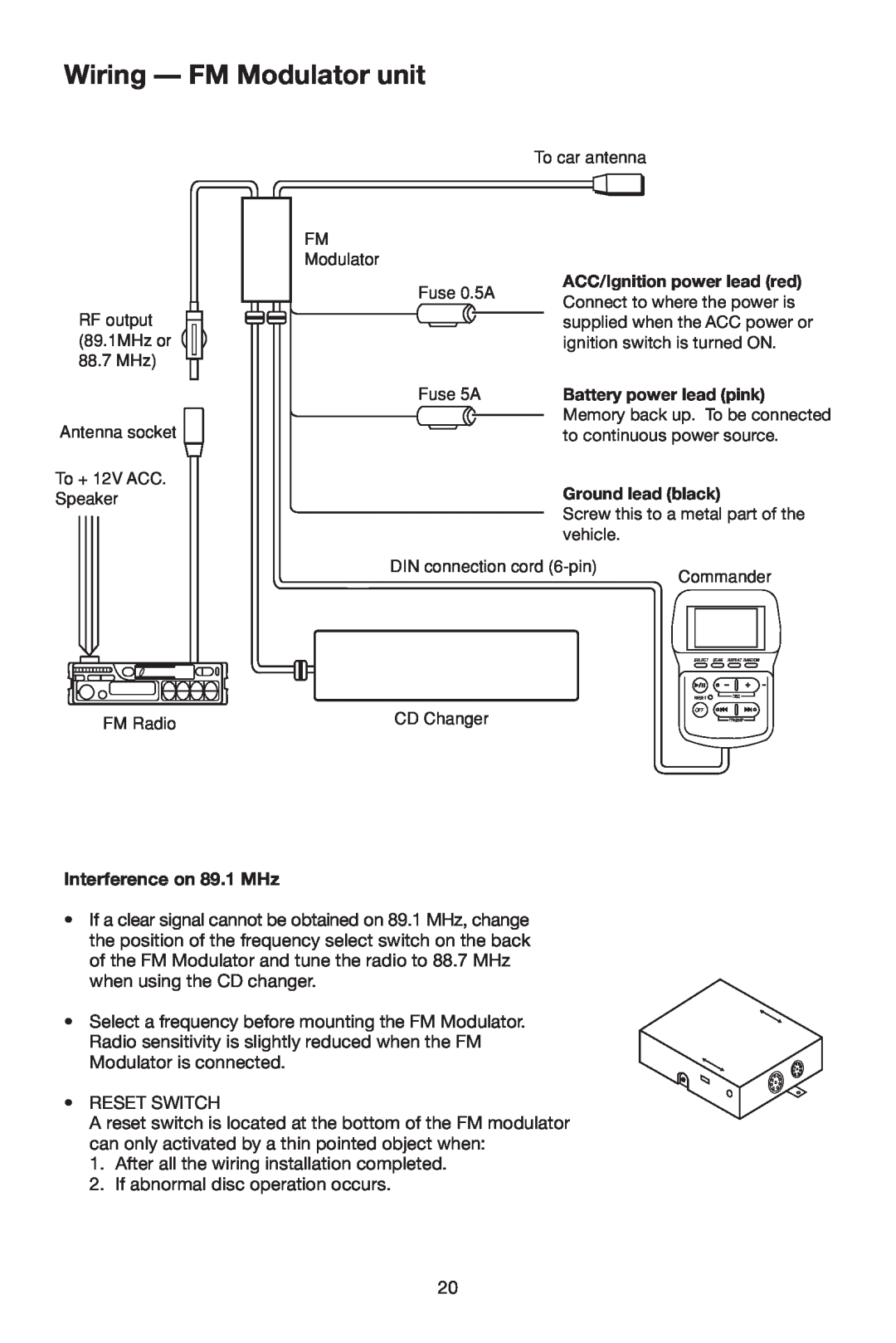
WIRING
RESET FUNCTION
Some functions do not operate Reset button
Transport Lock Screws
BEFORE INSTALLING THE UNIT
Installation and Wiring Precautions
Position of the built-in anti-vibrationboard
For use when unit is installed vertically
For use when unit is installed at a 45 angle
INSTALLATION
Pull back the carpet and determine
Set the built-in anti-vibrationboards
Procedure for Installation Suspended Position
TROUBLESHOOTING
Symptom
HANDLING THE DISCS
Cause
CD Changer Remote Control System
RESETDISC
OPERATING INSTRUCTIONS
SELECT SCAN REPEAT RANDOM
PARTS AND THEIR FUNCTIONS
Control section
Liquid Crystal Display LCD
Select Button
Power Button Power On/Off
Random Play Button Track or DISC Random
Play/Pause Button Play/Pause
Disc Selection Button +
Reset Button
Reset button
BEFORE USING THE SYSTEM
SETTING UP FOR OPERATION
Wiring - Using FM Modulator
Power ON and Play
CD CHANGER OPERATION
Listening to the CD Play
Playing in Other Modes
Playing a CD
Installation of the FM Modulator/Ground Isolator
Procedure To Mount The CD Changer Commander unit
Listening to the radio or tape
Random play
Wiring - FM Modulator unit
Interference on 89.1 MHz
Control and Function Keys
1.+12V TO IGNITION
2.ANTENNA
3.GROUND - /BACK UP
5.RESET FOR MODULATOR FUNCTION ONLY
7.CD CHANGER COMMANDER
4.OUTPUT FREQUENCY
6.CD CHANGER
Error Messages showing on display of controller
TROUBLESHOOTING
Symptom
Cause
88-D0040-14
Top
Page
Image
Contents