Converged Network Adapter
User’s Guide
8200 and 3200 Series
Changes
Document Revision History
Sections Affected
Quick Start
What is a Converged Network Adapter?
What is an Intelligent Ethernet Adapter?
Preface
1-14
1-11
1-12
1-13
1-22
Configuring NIC
1-20
1-21
2-20
Configuring iSCSI
2-15
2-19
Deploying the Driver
3-10
Configuring FCoE
2-24
A Adapter LEDs Glossary List of Figures
Page
2-23
2-10
List of Tables
2-47
2-58
What’s in This Guide
Preface
Related Materials
See “Installation Checklist” on page
Under Notification Options, select the Warning Alarms check box
Intended Audience
Technical Support
License Agreements
Support Headquarters
Training
Contact Information
Knowledge Database
Agency Certification
Warranty
Laser Safety
Legal Notices
CNS 13438 Class A QLE8xxx
CE Mark 2004/108/EC EMC Directive compliance
MIC Class A
2006/95/EC low voltage directive 8200 and 3200 Series Adapters
Product Safety Compliance
xviii
Step 2. Install the Adapter Hardware
Installation Instructions
Step 1. Verify the Package Contents
Step 1. Verify the Package Contents
Figure i Illustration of Server Motherboard and Slots
Step 2. Install the Adapter Hardware
Step 3. Install the Adapter Drivers
Additional Resources
Step 4. Install QConvergeConsole
Features
What is a Converged Network Adapter?
What is an Intelligent Ethernet Adapter?
Functionality and Features
Multi-boot capability including Preboot-eXecution environment PXE
Supported Operating Systems
Adapter Specifications
Physical Characteristics
Standards Specifications
Operating
Environmental Specifications
Table 1-1. Environmental Specifications
Condition
QLogic Linux SuperInstaller
Converged Network Adapter SuperInstaller Installation
Multi-boot Image for 10Gb CNA-CNA Function Configuration Utility
QLogic Windows SuperInstaller
Using QLflash
Converged Network Adapter Function Configuration Package Contents
Updating the Multi-boot Code
QLflash Options
QLflash Command Line Options
Function Type MinBW% Protocol
Adapter Configuration CNA/IEA Function Configuration Utility
Restore to Non-NIC Partition Settings
Exit the CNA Function Configuration Utility
Function
Adapter Settings
Primary/Secondary Target Settings
Initiator Settings
Protocol
Restore to Non-NIC Partition Settings
Type
MinBW%
Installing the Flash Utility Updating the Flash
Installing the QLogic Adapter vCenter Plug-in for ESX/ESXi
Exit the CNA Function Configuration Utility
Installing the QLogic Adapter CIM Provider
Figure 1-1. vSphere Client Showing QLogic Adapter Tab
Introduction
http\\driverdownloads.qlogic.com
Requirements
Figure 1-2. vCenter Plug-in Requirements
ESX/ESXi Server
vCenter Server
Installing the QLogic Adapter CIM Provider
Initial Installation
Initial Installation Subsequent Update Installation
Starting the QLogic Adapter CIM Provider
Subsequent Update Installation
# vihostupdate.pl connoptions --query\
Removing the QLogic Adapter CIM Provider
# esxupdate query --vib-view grep qlogic
# esxupdate remove -b vibID
Removing the QLogic Adapter vCenter Plug-in
Starting the QLogic Adapter vCenter Plug-in
1. In the Windows Control Panel, select Add or Remove Programs
Updating the Flash
Installing the Flash Utility
3. In the Select Flash File for Update dialog box, click Browse
5. In the Select Flash File for Update dialog box, click Send
http//tomcat.apache.org
Using the vCenter Plug-in on a Tomcat Server
Installing Tomcat on Linux Starting and Stopping Tomcat on Linux
Installing Tomcat on Windows
Installing Tomcat on Windows
Installing Tomcat on Linux
Starting and Stopping Tomcat on Linux
http//communities.vmware.com/docs/DOC-4521
Plug-in Unregistration from a Manual Installation
Installing the vCenter Plug-in on Tomcat
Starting and Stopping Tomcat on Windows
http//communities.vmware.com/docs/DOC-4530
Launching the Plug-in from vSphere Client
1-24
Packaging Content
2 Configuring NIC
Installing NIC in Linux
Installing NIC in ESX
ESX OS Support
Installing NIC in Windows
Windows OS Support
4. Set the Embedded NIC1 option to Enabled with PXE
Configuring PXE Boot
Figure 2-1. Dell BIOS Integrated Devices
3. Set the Embedded NIC1 and NIC2 option to Enabled
10. During POST, press the F2 key to enter the BIOS system
Figure 2-2. QLogic 8200 CNA Function Configuration
8. Press the ESC key to exit
11. Select Boot Settings, and then press the ENTER key Figure
Figure 2-3. BIOS Boot Settings
12. Select the Boot Sequence option, and then press the ENTER key
Overview
Configuring Driver Software Parameters
Linux NIC Driver Management Applications
Figure 2-4. Embedded NIC 1 QLogic PXE
Examples
Example RPM package installation
qaucli Utility
ethtool Utility
In the following example, ethtool ethn lists interface settings
Sample Output
phantomcore Utility
Windows Property Pages
b. In the Computer Management dialog box, click Device Manager
Property
Table 2-1. Windows Driver Configurable Parameters
Description
Table 2-1. Windows Driver Configurable Parameters Continued
Property
Table 2-1. Windows Driver Configurable Parameters Continued
Description
Property
Configuring NIC Driver Parameters with QCC Non-Interactive CLI
VLAN Configuration
Configuring NIC Driver Parameters with QCC GUI
Configuring NIC Driver Parameters with QCC Interactive CLI
Teaming Modes
Switch
System Fault
Team MAC Address
Failsafe Mode
Table 2-2. Windows Teaming Modes Continued
Link Aggregation Mode
Switch-Independent Load Balancing Mode
Dynamic Link Aggregation DLA
Static Link Aggregation SLA
Using the Team Management GUI
Using the CLI for Teaming
Figure 2-5. Team Management Property Page
Teaming Configuration
Creating a Team Modifying a Team Deleting a Team
Saving and Restoring Teaming Configuration
Creating a Team
Figure 2-6. Creating a Team
Name-Type a name for the new team
The following figures show the configuration of various teaming modes
Figure 2-7. Creating a Failsafe Team
2-24
Figure 2-8. Creating a Switch-Independent Load Balancing Team
2-25
Figure 2-9. Creating an 802.3ad Static Team
2-26
Figure 2-10. Creating an 802.3ad Dynamic Team
Modifying a Team
Figure 2-11. Confirming New Team Creation
Figure 2-12. Adding a Team
Figure 2-13. Modifying Advanced Team Properties
The team properties change takes effect immediately. Changing team properties causes the driver to reload, which could result in a momentary loss of connectivity
To modify team composition
Figure 2-14. Modifying Team Properties
2. On the shortcut menu, click Modify Team Figure
Example
Figure 2-15. Modifying Failsafe Team Properties
Deleting a Team
Figure 2-16. Modifying the Team Type
Viewing Teaming Statistics
Saving and Restoring Teaming Configuration
Linux Bonding/Failover/Aggregation
NIC Partition NPAR
Configuration and Operation
Using NPAR under ESX
Configuring NPAR in QCC Non-Interactive CLI
Configuring NPAR in the BIOS
Configuring NPAR in QCC GUI
Configuring NPAR in QCC Interactive CLI
Figure 2-18. 8200 Series Configuration Range Without NPAR
Figure 2-17. vCenter Plug-in QLogic Adapter Tab Default View
Figure 2-20. 3200 Series Configuration Range With NPAR
Figure 2-19. 8200 Series Configuration Range With NPAR
Figure 2-21. Enabling a Physical Function
3. Click Save Configuration
6. Click the QLogic Adapter tab
NPAR Personality Changes
Figure 2-22. Port One Configured with NPAR Enabled
Enabling NPAR
Quality of Service
eSwitch
Configuration, and eSwitch Statistics
Running Linux User Diagnostics
NIC TroubleShooting/Diagnostics
NIC Linux Diagnostics
Linux Diagnostics
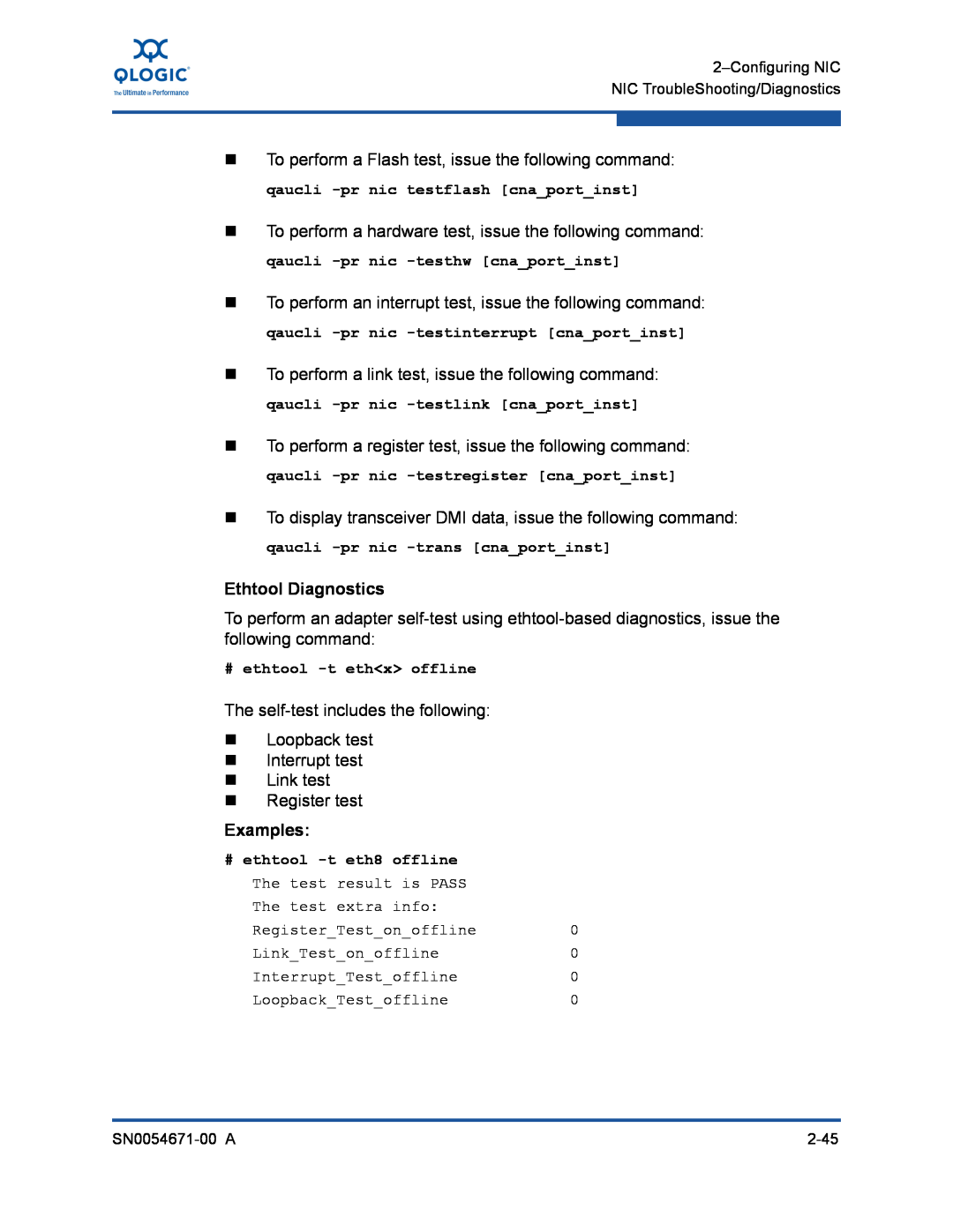
The self-test includes the following Loopback test Interrupt test
Ethtool Diagnostics
Running Windows User Diagnostics
Windows Property Page Diagnostics
Linux Diagnostic Test Descriptions
Linux Diagnostic Test Messages
Figure 2-24. Diagnostics Tests on Windows
Table 2-4. Windows QConvergeConsole CLI-Selecting a Protocol in
Command
Table 2-3. Windows QConvergeConsole CLI-Selecting a Protocol in
Menu Mode
Table 2-5. Windows QConvergeConsole CLI-Getting Help
Table 2-6. Windows QConvergeConsole CLI-Miscellaneous Commands
Table 2-7. Windows QConvergeConsole CLI-Diagnostic Test Commands
Legacy Mode Continued
Commands Continued
Table 2-7. Windows QConvergeConsole CLI-Diagnostic Test
Test Type
Table 2-8. Running Windows Diagnostic Tests in the CLI
Interrupt Test
Windows Diagnostic Test Descriptions
Hardware Test
Register Test
Test
Windows Diagnostic Test Messages
Table 2-9. Windows Diagnostic Test Messages
Error Message
Table 2-9. Windows Diagnostic Test Messages Continued
For example
Refer to the QConvergeConsole Users Guide for information
QCC GUI Diagnostics
QCC CLI Diagnostics QCC Interactive CLI
QCC CLI Diagnostics QCC Non-Interactive CLI
Figure 2-25. NIC Troubleshooting Diagram
NIC Troubleshooting Guidelines
2-58
Figure 2-26. NIC Troubleshooting Diagram
Deploying the Driver
3 Configuring iSCSI
Installing iSCSI in Linux
iSCSI Overview
Installing iSCSI in Windows
Installing iSCSI in ESX
Installing the Driver
iSCSI Configuration with Non-Interactive CLI
iSCSI Configuration
iSCSI Configuration with QCC GUI
iSCSI Configuration with Interactive QCC CLI
14. Select 6, Add a Target
Configuring an iSCSI Initiator in Windows
14. Select 6, Add a Target
6. Click Configure
iSCSI Boot
Configuring an iSCSI Initiator in VMware
iSCSI Boot Setup Using Fast!UTIL
Accessing Fast!UTIL
DHCP Boot Setup for iSCSI Boot
Configuring iSCSI Boot Settings
Configuring iSCSI Boot using Interactive QCC CLI
iBFT Boot Setup
iSCSi Boot Setup Using QCC CLI
Configuring iSCSI Boot using the QCC CLI
iSCSI Diagnostics using Interactive QCC CLI
iSCSI TroubleShooting
iSCSI Diagnostics
iSCSI Diagnostics using QCC GUI
Figure 3-1. iSCSI Troubleshooting Diagram
iSCSI Troubleshooting Diagram
Packaging Content
4 Configuring FCoE
Installing FCoE
Installing FCoE in Linux
Using the Driver
Installing FCoE in ESX
Installing FCoE in Windows
Firmware Installation
Setting HBA Parameters with the Non-Interactive QCC CLI
Boot Devices Configuration
Setting HBA Parameters with the QCC GUI
Setting HBA Parameters with the Interactive QCC CLI
Configuring NPIV with the Non-Interactive QCC CLI
Configuring Boot Devices with the BIOS
Configuring NPIV with the QCC GUI
Configuring NPIV with the Interactive QCC CLI
FCoE Diagnostics
Troubleshooting
Configuring Selective LUNS with the Interactive QCC CLI
Configuring Selective LUNS with the Non-Interactive QCC CLI
Figure 4-1. FCoE Troubleshooting Diagram
FCoE Troubleshooting Diagram
Activity LED
A Adapter LEDs
Table A-1. QLE824x and QLE324x LED Scheme
Link LED
A-Adapter LEDs
challenge-handshake authentication protocol CHAP
Basic input output system BIOS
boot device
boot from SAN
Enhanced Ethernet
dynamic host configuration protocol DCHP
device
driver
loopback
message signaled interrupts MSI/MSIX
Nonvolatile random access memory NVRAM
logical unit number LUN
port instance
quality of service QoS
PCIe PCI Express
port
UEFI
transmission control protocol/Internet protocol TCP/IP
worldwide port name WWPN
Glossary-6
Page
949.389.6000
Corporate Headquarters QLogic Corporation
26650 Aliso Viejo Parkway
Aliso Viejo, CA