PART 1 - PACKAGE CONTENTS
| 4 or 8 | Manual and |
QC40108 DVR | Color Cameras with Stands | Software CD |
manuals and software
QC Series
| Video/Audio Dongle |
| Ethernet | |
Hard Drive |
|
| Cable | |
|
|
|
|
|
Power Supply |
| Power Supply & 4- or |
| Video and Power |
|
| Camera Cable | ||
for DVR |
|
| ||
|
| (One per Camera) | ||
|
|
|
|
|
|
|
|
|
|
USB 2.0 | Remote | |
Mouse | Control | |
|
|
|
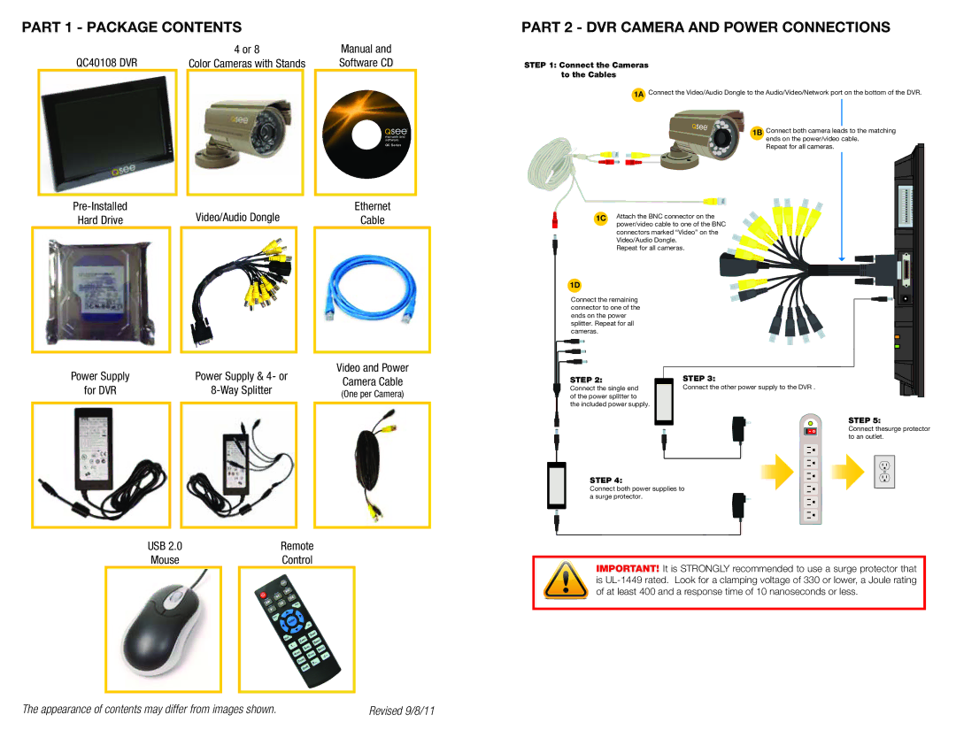
PART 2 - DVR CAMERA AND POWER CONNECTIONS
STEP 1: Connect the Cameras to the Cables
1A Connect the Video/Audio Dongle to the Audio/Video/Network port on the bottom of the DVR.
1B Connect both camera leads to the matching ends on the power/video cable.
Repeat for all cameras.
Rx Tx
A B |
Attach the BNC connector on the | NO C | |
2 | ||
1C power/video cable to one of the BNC | 4 | |
3 | ||
1 | ||
connectors marked “Video” on the |
| |
Video/Audio Dongle. |
|
|
Repeat for all cameras. |
| |
|
| AUDIO/VIDEO/NET |
1D |
|
|
Connect the remaining |
| DC 12V |
connector to one of the |
|
|
ends on the power |
|
|
splitter. Repeat for all |
|
|
cameras. |
|
|
STEP 2: | STEP 3: |
|
Connect the single end | Connect the other power supply to the DVR . |
|
of the power splitter to |
|
|
the included power supply. |
|
|
|
| STEP 5: |
|
| Connect thesurge protector |
|
| to an outlet. |
STEP 4:
Connect both power supplies to a surge protector.
IMPORTANT! It is STRONGLY recommended to use a surge protector that is
The appearance of contents may differ from images shown. | Revised 9/8/11 |