Contents
Page
Safety Precautions
About this document
Warranty and Service
Before reading this document
Strong recommendation on installation of the DVR unit
CONTENTS
1. FEATURE AND FUNCTION
2. UNIT DESCRIPTION OF FRONT PANEL
2.1 Recording/Playing Control Buttons Area
2.2 Function Control Area
1. Auto/1 Auto key, in shift mode, press this button, The DVR will be in auto dwell state, it dwells according to the time set in auto sequence set menu, and you can set the dwell time of each channel. Press this button to quit this mode. If not in shift mode, press this button to see big picture of channel 1. While inputting numbers, this button is used as number key of “1”
2.3 Channel Choosing Control Area
3. REAR PANEL AND SYSTEM CONNECTION
3.3 Alarm Connection
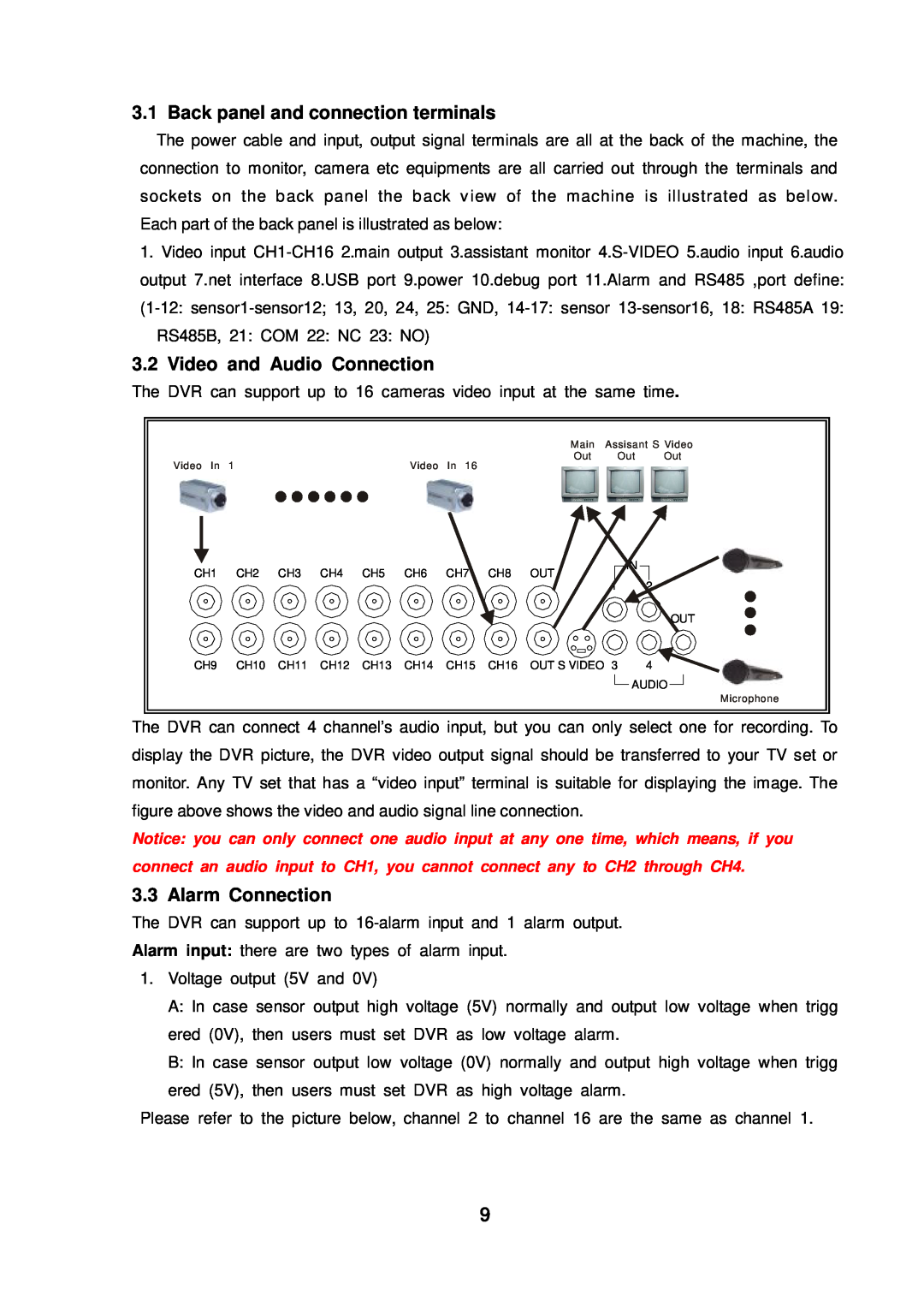
3.1 Back panel and connection terminals
3.2 Video and Audio Connection
Alarm output
There are processing to install the hard disk
3.4 Hard Disk Connection
4. REMOTE CONTROLLER
5. SYSTEM SETUP
5.1 SETUP MENU
Page
5.2.1 TIME/DATA SET
5.2 SYSTEM SETUP
5.2.2 HDD FORMAT SET
5.2.3 FACTORY RESET
5.2.4 Change Password
5.2.5 Firmware Update
5.3.1 CAMERA NAME SET
5.3 DISPLAY SETUP
5.3.2 COLOR SET
5.3.3. AUTO SEQUENCE SET
5.4 RECORD SETUP
5.4.1 AUDIO CH SET
5.4.2 REC CH SET
5.5 NETWORK SETUP
5.5.1. N/W ENABLE SET
5.5.2. MAC SET
5.6 SENSOR SETUP
5.6.1 Motion Detection settings
1 When surveying nearby objects 2-10 meters
2 When surveying objects in 50-100 meters area
5.6.2 MOTION AREA SET
5.7 SCHEDULE SET
5.8 USB BACKUP
5.10 PTZ SET
5.9 STORAGE INFO
6.1 Start the DVR
6. Quick User Guideline
6.2 Turn off the DVR
6.3 Normal Recording
6.4 Alarm Recording
6.5 Time Recording
6.6 Playback
6.7 Search Play
6.9 Event Search
6.8 Time Search
6.10 Record Search
6.11 USB Backup
6.13 Zoom Operation
6.12 USB Update
6.15 PTZ Operation
6.14 Information Display
Press the PTZ button one more time to exit from PTZ control
6.16 REMOTE CONTROLLER
7. USING THE NETWORK VIEWER
7.2 Viewer connect
7.1 Setting
Please click button, you will see the window below
Enter the IP address and click “OK” button
7.4 Playback
7.3 Live play
7.6 File Play
7.5 Scandisk
7.7 Save to AVI
7.9 PTZ Control
7.8 Save to DVR
8. Main standard & parameter chart
9. Trouble shooting guide
Q. Why cannot I access Network Set menu?
A. Please stop record or play before you access these menu
Q. I press record button, but the DVR does not start recording, why?
Q. There is a movement, but the DVR does not start recording
10. Record Time Table
Resolution
Rec rate field/sec
Picture quality
11. Internet View/Playback Configurations
11.2 Network Configurations
11.1 About Networks
Page
Page
Q-SEE Product Warranty
Customer Information Card User’s NameMr./Mrs Company Name Postal
Address Postal code Phone Number E-mail Model Number of Product
Serial Number of Product Purchase Date Distributor