|
|
|
|
| Appendix |
|
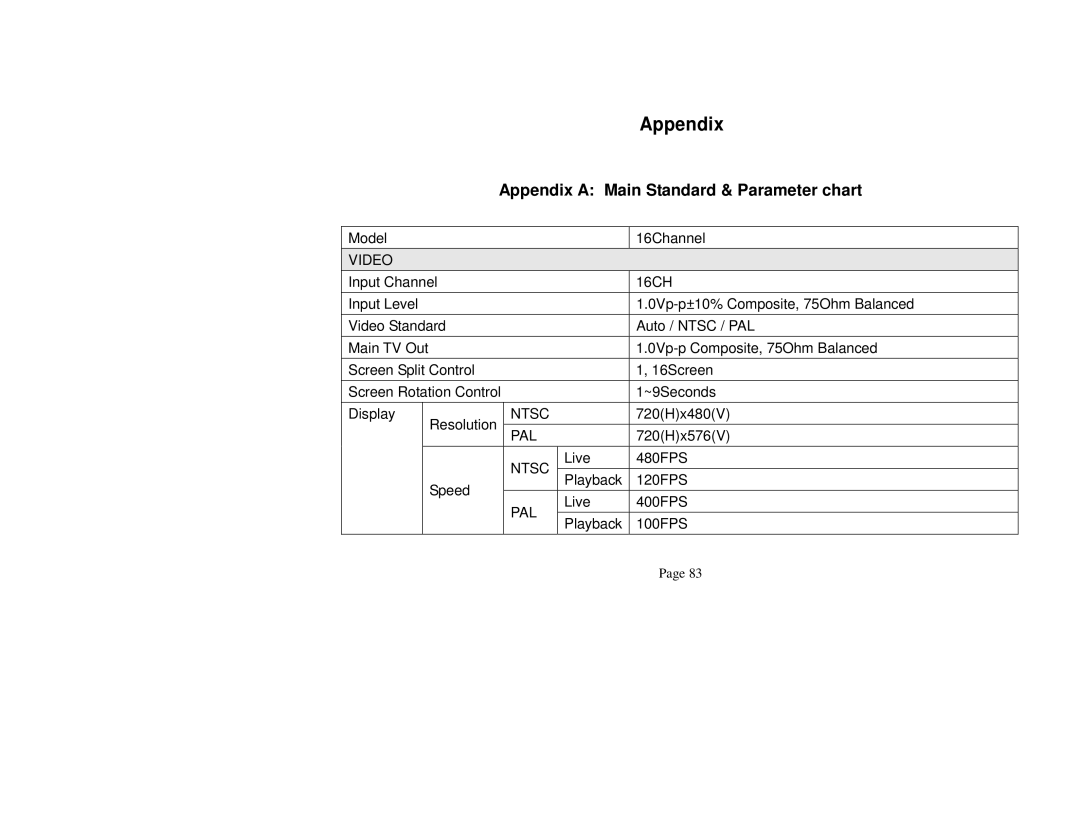
| Appendix A: Main Standard & Parameter chart | |||
|
|
|
|
|
|
Model |
|
|
| 16Channel | |
|
|
|
|
|
|
VIDEO |
|
|
|
| |
|
|
|
|
|
|
Input Channel |
|
|
| 16CH | |
|
|
|
|
|
|
Input Level |
|
|
| ||
|
|
|
|
|
|
Video Standard |
|
|
| Auto / NTSC / PAL | |
|
|
|
|
|
|
Main TV Out |
|
|
| ||
|
|
|
|
|
|
Screen Split Control |
|
|
| 1, 16Screen | |
|
|
|
|
| |
Screen Rotation Control | 1~9Seconds | ||||
|
|
|
|
|
|
Display | Resolution |
| NTSC | 720(H)x480(V) | |
|
|
|
|
| |
| PAL | 720(H)x576(V) | |||
|
|
| |||
|
|
|
|
|
|
|
|
| NTSC | Live | 480FPS |
|
|
|
|
| |
| Speed |
| Playback | 120FPS | |
|
|
| |||
|
|
|
|
| |
|
| PAL | Live | 400FPS | |
|
|
| |||
|
|
|
|
| |
|
|
| Playback | 100FPS | |
|
|
|
| ||
|
|
|
|
|
|
Page 83