1200, 1700, 1400, 1100 specifications
QSC Audio has long been a revered name in professional audio, and its series of amplifiers—including the QSC 1100, 1200, 1400, and 1700—continues to showcase the brand's commitment to quality, performance, and innovation. Each model is designed to meet the diverse needs of audio professionals, whether for live sound, installations, or studio use.The QSC 1100 amplifier is renowned for its lightweight and compact design while delivering a solid 1100 watts of power. It features QSC's advanced Class D technology, which not only provides high efficiency but also significantly reduces heat generation. The 1100 includes comprehensive protection circuitry, ensuring safe operation in all situations. With a Frequency Response of 20 Hz to 20 kHz, the amplifier offers a balanced and clear sound profile, making it suitable for various applications.
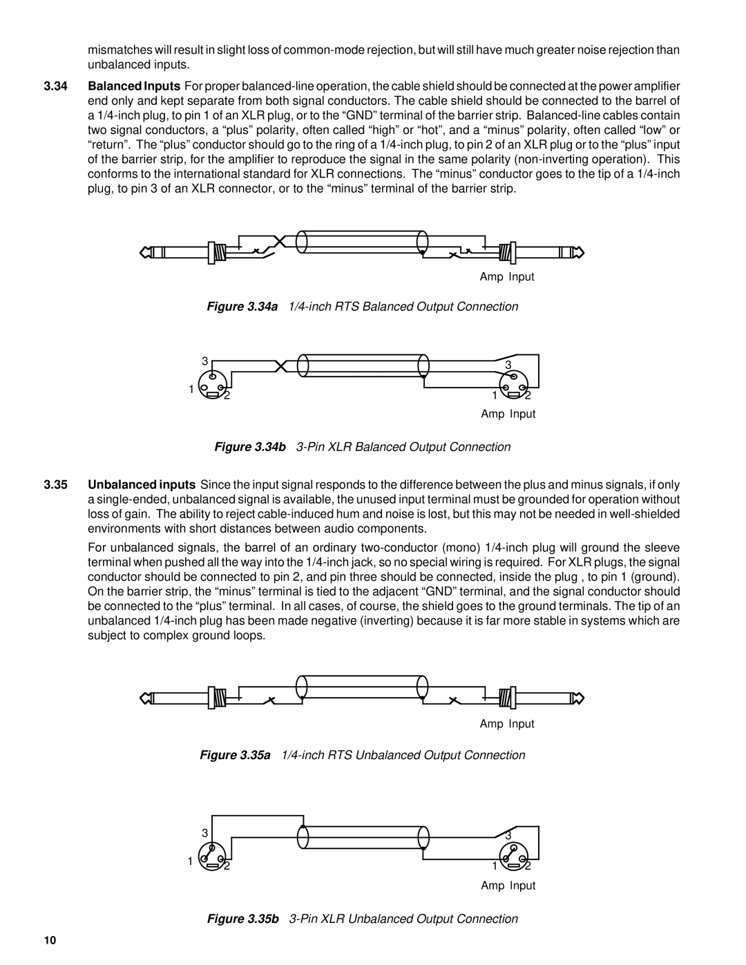
Moving up the line, the QSC 1200 offers increased power output at 1200 watts and comes equipped with advanced DSP (Digital Signal Processing). The DSP allows users to tailor the audio output precisely, delivering optimized performance for any setting. In addition to its robust power, the 1200 features a versatile input section, supporting both XLR and 1/4" TRS connectors, providing flexibility for any audio source.
The QSC 1400 amplifier is a workhorse in the series, capable of producing up to 1400 watts, making it ideal for larger venues and events. This model is designed with enhanced thermal management, ensuring reliability even during extended use. The 1400’s high-frequency response capabilities further improve its adaptability, handling complex audio signals with ease.
Lastly, the QSC 1700 stands as the powerhouse of this lineup, delivering a remarkable 1700 watts of clean, distortion-free audio. It boasts an advanced cooling system, making it perfect for high-demand environments. The 1700 is also equipped with customizable limiter settings, allowing users to protect their speakers while maintaining sound integrity.
QSC’s commitment to durability is evident in all four amplifiers, featuring rugged chassis designs and high-quality components to withstand the rigors of professional use. Collectively, the QSC 1100, 1200, 1400, and 1700 amplifiers offer a compelling range of features that cater to various audio needs, all while ensuring superior sound quality and reliability, making them excellent choices for any sound engineer or venue manager.

