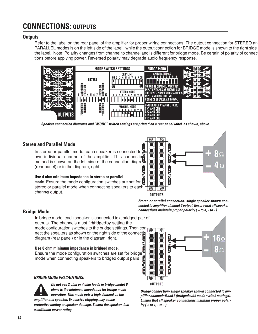
CONNECTIONS: OUTPUTS
Outputs
Refer to the label on the rear panel of the amplifier for proper wiring connections. The output connection for STEREO and PARALLEL modes is on the left side of the label , while the output connection for BRIDGE mode is shown to the right side of the label. Note: Polarity changes from channel to channel and is different for bridge mode. Be certain of polarity of connec- tions before applying power. Reversed polarity may degrade audio frequency response.
Speaker connection diagrams and “MODE” switch settings are printed on a rear panel label, as shown, above.
Stereo and Parallel Mode
In stereo or parallel mode, each speaker is connected to its own individual channel of the amplifier. This connection method is shown on the left side of the connection diagram (rear panel) or in the diagram, right.
Use 4 ohm minimum impedance in stereo or parallel mode. Ensure the mode configuration switches are set for stereo or parallel mode when connecting speakers to each channel’s output.
Bridge Mode
In bridge mode, each speaker is connected to a
Use 8 ohm minimum impedance in bridged mode. Ensure the mode configuration switches are set for bridge mode when connecting speakers to bridged output pairs .
BRIDGE MODE PRECAUTIONS:
Do not use 2 ohm or 4 ohm loads in bridge mode! 8 ohms is the minimum impedance for bridge mode operation. This mode puts a high demand on the
amplifier and speaker. Excessive clipping may cause protective muting or speaker damage. Ensure the speaker has a sufficient power rating.
Stereo or parallel connection- single speaker shown con- nected to amplifier channel 6 output. Ensure that all speaker connections maintain proper polarity ( + to +, - to - ).
Bridge connection- single speaker shown connected to am- plifier channels 5 and 6 (bridged with mode switch settings). Ensure that all speaker connections maintain proper polar- ity ( + to +, - to - ).
14