DSP-30 specifications
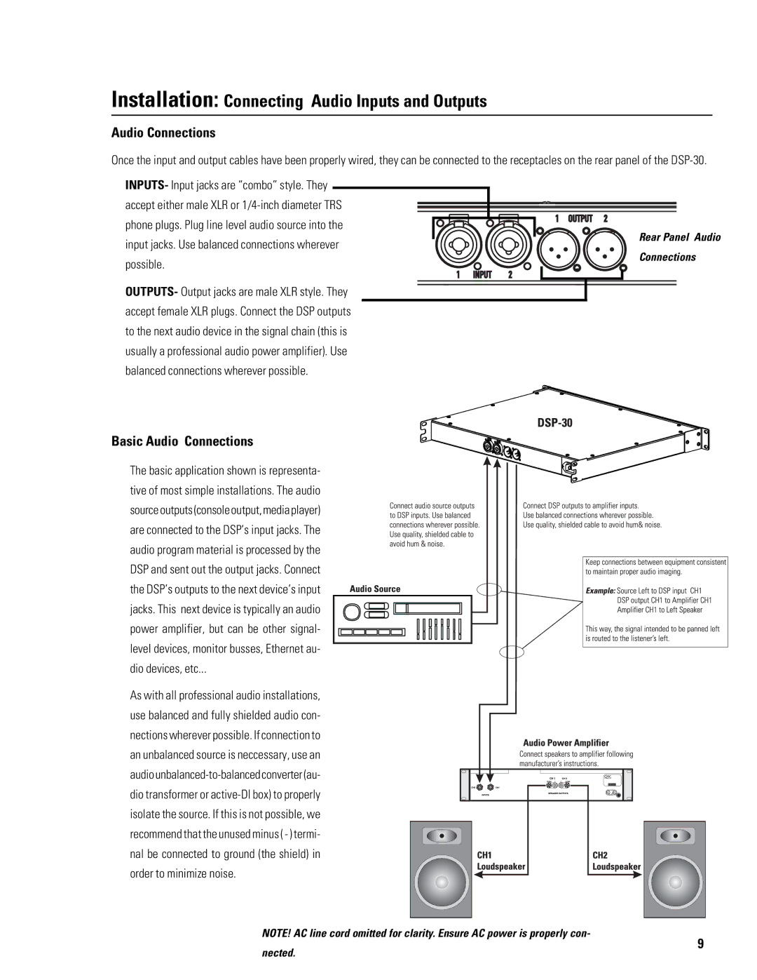
The QSC Audio DSP-30 is a powerful digital signal processing platform designed for a wide range of audio applications, particularly in professional audio environments such as live sound, installation, and broadcast. Renowned for its exceptional audio performance and versatility, the DSP-30 provides users with advanced control over audio signals, ensuring that sound quality meets the highest standards.One of the standout features of the DSP-30 is its robust processing capabilities. With up to 30 channels of audio processing, it allows users to manipulate both live and recorded audio seamlessly. The unit supports various input and output configurations, giving sound engineers the flexibility to adapt to multiple setups and environments.
The DSP-30 incorporates an array of advanced algorithms and processing tools, including equalization, compression, limiting, and delay functionality. These tools enable users to fine-tune audio signals for optimal clarity and impact, ensuring that performances remain consistent and engaging regardless of the venue size or acoustics.
Moreover, the DSP-30 utilizes QSC's exclusive Intrinsic Correction technology, which optimizes loudspeakers for their specific acoustic environment. This feature helps to eliminate unwanted resonances and provide an enhanced listening experience. By tailoring the audio output to the room's characteristics, the DSP-30 ensures uniform sonic quality throughout the space.
In addition, the device boasts comprehensive networking capabilities. With built-in support for Q-SYS and Dante protocols, users can easily integrate the DSP-30 into existing audio networks. This connectivity allows for remote management and control, enhancing workflow efficiency and enabling system monitoring from virtually anywhere.
The user interface of the DSP-30 is designed for ease of use, featuring a clear display and intuitive navigation. Users can effortlessly configure their audio settings and access presets designed for various applications, from small presentations to large-scale concerts.
Durability and reliability are paramount in the DSP-30’s design. Built with high-quality components, the unit is engineered to withstand the rigors of regular use in demanding environments, making it a trusted choice for audio professionals.
Overall, the QSC Audio DSP-30 combines innovative technologies with a user-friendly interface, making it an essential tool for anyone looking to achieve exceptional audio performance in a variety of settings. Its flexibility, advanced processing features, and integration capabilities position it as a leader in the digital audio processing domain.

