I-82H Introduction
Thank you and congratulations on your purchase of the ISIS Series
The
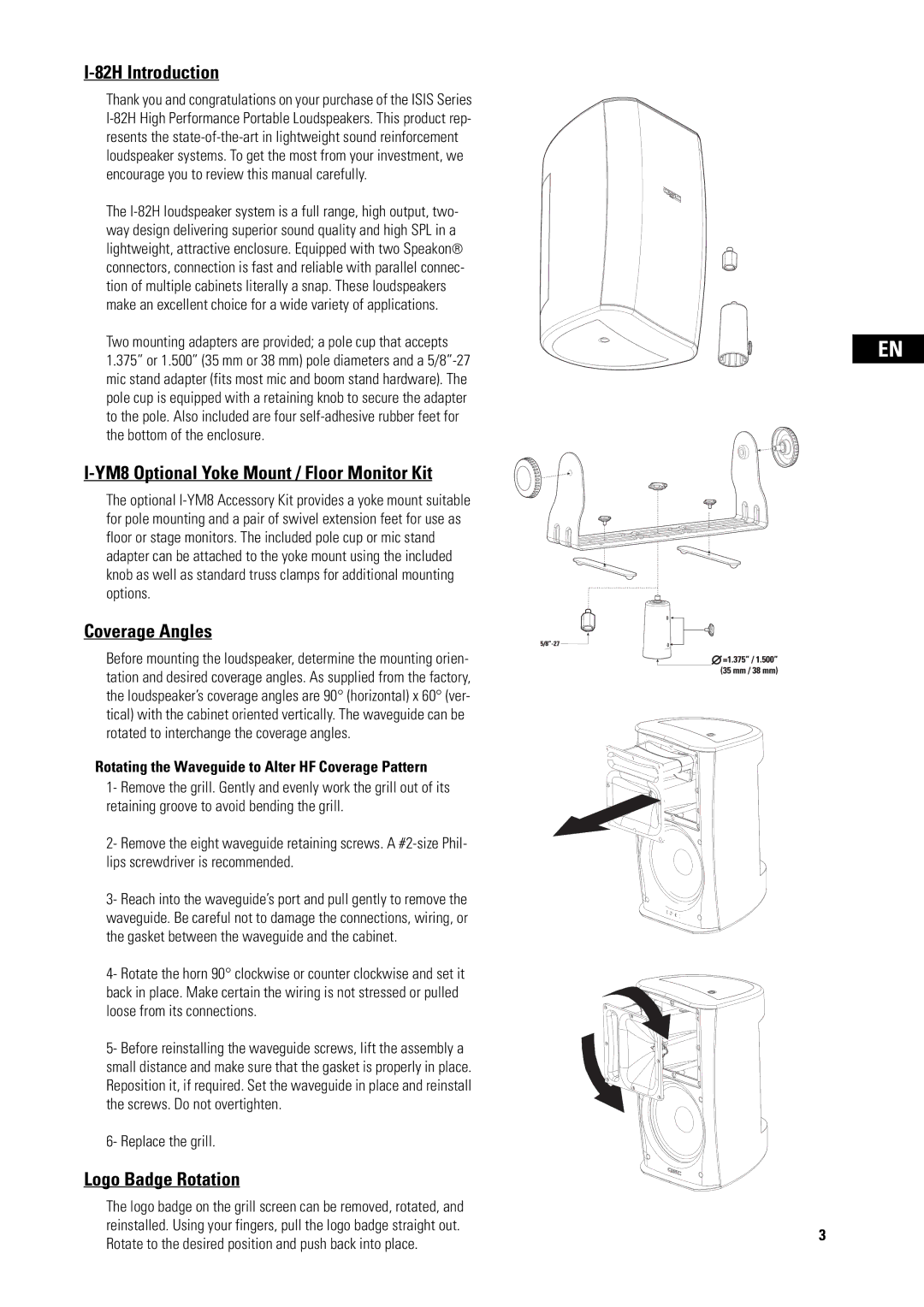
Two mounting adapters are provided; a pole cup that accepts 1.375” or 1.500” (35 mm or 38 mm) pole diameters and a
I-YM8 Optional Yoke Mount / Floor Monitor Kit
The optional
Coverage Angles
Before mounting the loudspeaker, determine the mounting orien- tation and desired coverage angles. As supplied from the factory, the loudspeaker’s coverage angles are 90° (horizontal) x 60° (ver- tical) with the cabinet oriented vertically. The waveguide can be rotated to interchange the coverage angles.
Rotating the Waveguide to Alter HF Coverage Pattern
1- Remove the grill. Gently and evenly work the grill out of its retaining groove to avoid bending the grill.
2- Remove the eight waveguide retaining screws. A
3- Reach into the waveguide’s port and pull gently to remove the waveguide. Be careful not to damage the connections, wiring, or the gasket between the waveguide and the cabinet.
4- Rotate the horn 90° clockwise or counter clockwise and set it back in place. Make certain the wiring is not stressed or pulled loose from its connections.
5- Before reinstalling the waveguide screws, lift the assembly a small distance and make sure that the gasket is properly in place. Reposition it, if required. Set the waveguide in place and reinstall the screws. Do not overtighten.
6- Replace the grill.
Logo Badge Rotation
EN
The logo badge on the grill screen can be removed, rotated, and reinstalled. Using your fingers, pull the logo badge straight out.
Rotate to the desired position and push back into place.
3