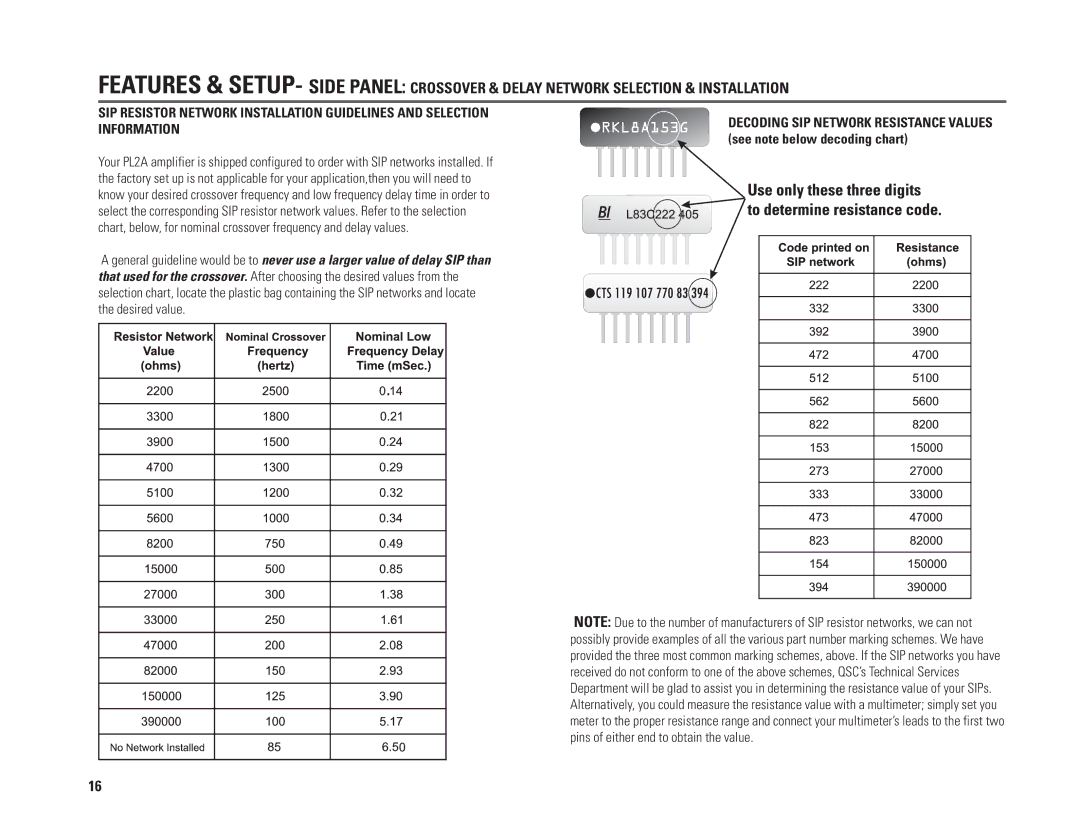
PL224A, PL236A, PL218A, PL230A specifications
QSC Audio is known for its high-quality professional audio equipment, and the PL series amplifiers are no exception. The PL236A, PL230A, PL218A, and PL224A are designed to meet the demands of live sound applications, touring, and installations, providing powerful, reliable, and efficient performance.The PL236A is a versatile power amplifier capable of delivering 800 watts per channel at 4 ohms, making it suitable for a variety of applications. It utilizes Class H technology, which boosts efficiency while minimizing heat generation, allowing for cooler operation and longer lifespan. The PL236A is equipped with QSC's Advanced Thermal Management technology, featuring variable-speed fans that adjust to the temperature, ensuring optimal performance under various conditions.
The PL230A is another exceptional model in the series, offering 600 watts per channel at 4 ohms. This amplifier is perfect for smaller systems or as part of a larger configuration. Its compact design makes it easy to transport, while its robust construction guarantees durability in demanding environments. Like the PL236A, it is also designed with Class H architecture and Advanced Thermal Management, providing both efficiency and reliability.
For those in need of sub-bass reinforcement, the PL218A is a dual 18-inch subwoofer amplifier that provides significant power output, reaching up to 2400 watts at 4 ohms. Its design focuses on low-frequency performance, ensuring that it can handle even the most demanding bass signals without distortion. The PL218A incorporates QSC’s patented Power Factor Correction technology, ensuring optimal energy consumption and minimizing electrical load.
Finally, the PL224A is a dual-channel amplifier with 1200 watts per channel at 4 ohms, designed with flexibility and scalability in mind. It is perfect for driving full-range systems or can be combined with additional amplification for larger setups. The PL224A features a comprehensive limiter section that protects speakers from over-excursion and ensures clean audio output.
All models in the QSC PL series come with user-friendly rear panel controls for easy setup and operation, along with input XLR connectors and speakON outputs for secure and efficient connections. The amplifiers also feature a robust chassis design for enhanced durability, and their lightweight construction allows for easy transport and installation.
In summary, the QSC PL236A, PL230A, PL218A, and PL224A amplifiers exemplify modern audio technology, offering powerful performance, flexibility, and reliability for a variety of professional audio applications. With their robust design and advanced features, these amplifiers are ideal for sound reinforcement in live settings and permanent installations alike.

