I I I . Y O U R P O W E R C H A I R
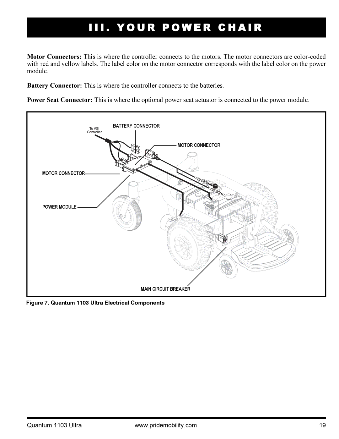
Motor Connectors: This is where the controller connects to the motors. The motor connectors are
Battery Connector: This is where the controller connects to the batteries.
Power Seat Connector: This is where the optional power seat actuator is connected to the power module.
BATTERY CONNECTOR |
MOTOR CONNECTOR |
MOTOR CONNECTOR |
POWER MODULE |
MAIN CIRCUIT BREAKER |
Figure 7. Quantum 1103 Ultra Electrical Components
Quantum 1103 Ultra | www.pridemobility.com | 19 |