I I I . Y O U R P O W E R C H A I R
Electronics Tray
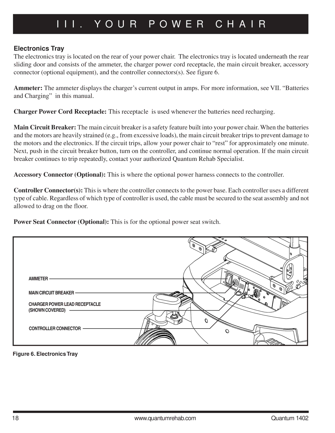
The electronics tray is located on the rear of your power chair. The electronics tray is located underneath the rear sliding door and consists of the ammeter, the charger power cord receptacle, the main circuit breaker, accessory connector (optional equipment), and the controller connectors(s). See figure 6.
Ammeter: The ammeter displays the charger’s current output in amps. For more information, see VII. “Batteries and Charging” in this manual.
Charger Power Cord Receptacle: This receptacle is used whenever the batteries need recharging.
Main Circuit Breaker: The main circuit breaker is a safety feature built into your power chair. When the batteries and the motors are heavily strained (e.g., from excessive loads), the main circuit breaker trips to prevent damage to the motors and the electronics. If the circuit trips, allow your power chair to “rest” for approximately one minute. Next, push in the circuit breaker button, turn on the controller, and continue normal operation. If the main circuit breaker continues to trip repeatedly, contact your authorized Quantum Rehab Specialist.
Accessory Connector (Optional): This is where the optional power harness connects to the controller.
Controller Connector(s): This is where the controller connects to the power base. Each controller uses a different type of cable. Regardless of which type of controller is used, the cable must be secured to the seat assembly and not allowed to drag on the floor.
Power Seat Connector (Optional): This is for the optional power seat switch.
AMMETER |
MAIN CIRCUIT BREAKER |
CHARGER POWER LEAD RECEPTACLE |
(SHOWN COVERED) |
CONTROLLER CONNECTOR |
Figure 6. Electronics Tray
18 | www.quantumrehab.com | Quantum 1402 |