HYDRAULIC CONNECTIONS
Unit water
•Temperature and pressure gauges for maintenance or servicing operations.
•Manual
•Metallic supply water filter to be sited at the inlet pipe, with a mesh not larger than 1 mm.
•Vent valves, expansion tank with water filling, discharge valve.
The water inlet must correspond with the connection labelled ”USER WATER INLET”, otherwise the evaporator may freeze.
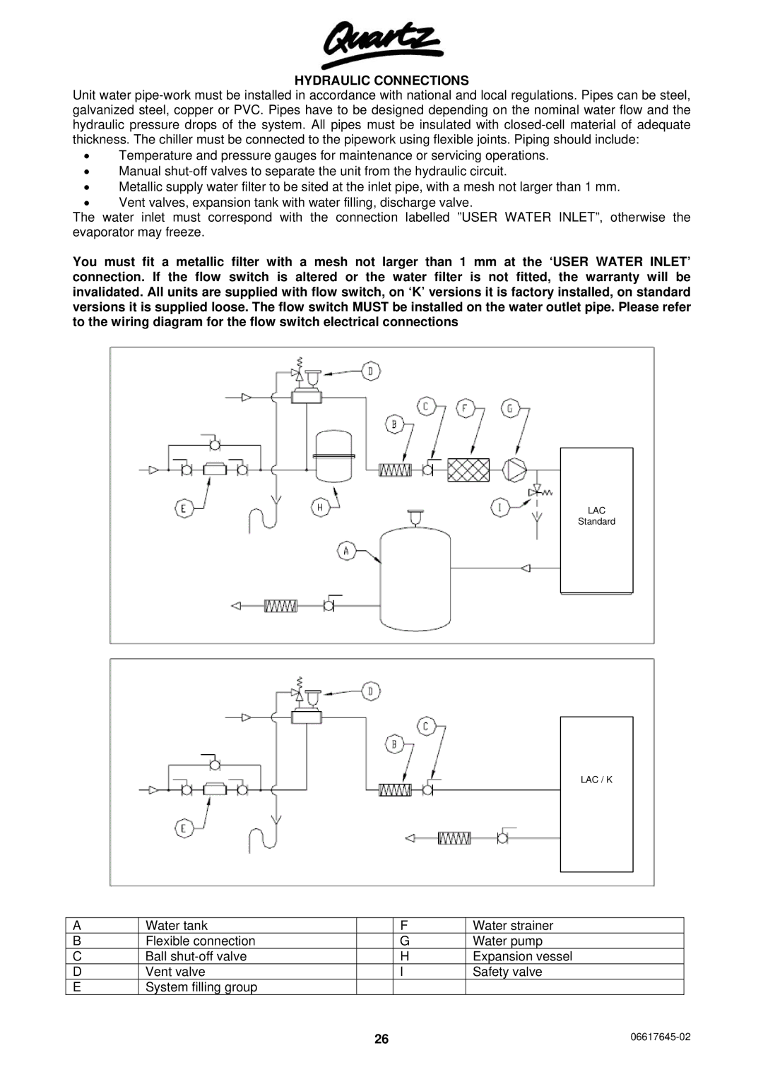
You must fit a metallic filter with a mesh not larger than 1 mm at the ‘USER WATER INLET’ connection. If the flow switch is altered or the water filter is not fitted, the warranty will be invalidated. All units are supplied with flow switch, on ‘K’ versions it is factory installed, on standard versions it is supplied loose. The flow switch MUST be installed on the water outlet pipe. Please refer to the wiring diagram for the flow switch electrical connections
LAC
Standard
LAC / K
A | Water tank |
| F | Water strainer |
|
B | Flexible connection |
| G | Water pump |
|
C | Ball |
| H | Expansion vessel |
|
D | Vent valve |
| I | Safety valve |
|
E | System filling group |
|
|
|
|
| 26 |
| |||