7 PCI Resource Map
Listed below are the PCI resources used by the
(all numbers in hex) |
|
|
PCI Vendor ID: | 0x135C | Quatech, Inc. |
PCI Device ID: | 0x01A0 | |
PCI Class Code |
|
|
Base class: | 0x07 | Simple communications controller |
Subclass: | 0x02 | Multiport serial controller |
Interface: | 0x00 |
|
IRQ sourced by: | INTA# |
|
Base Address and Interrupt Level (IRQ)
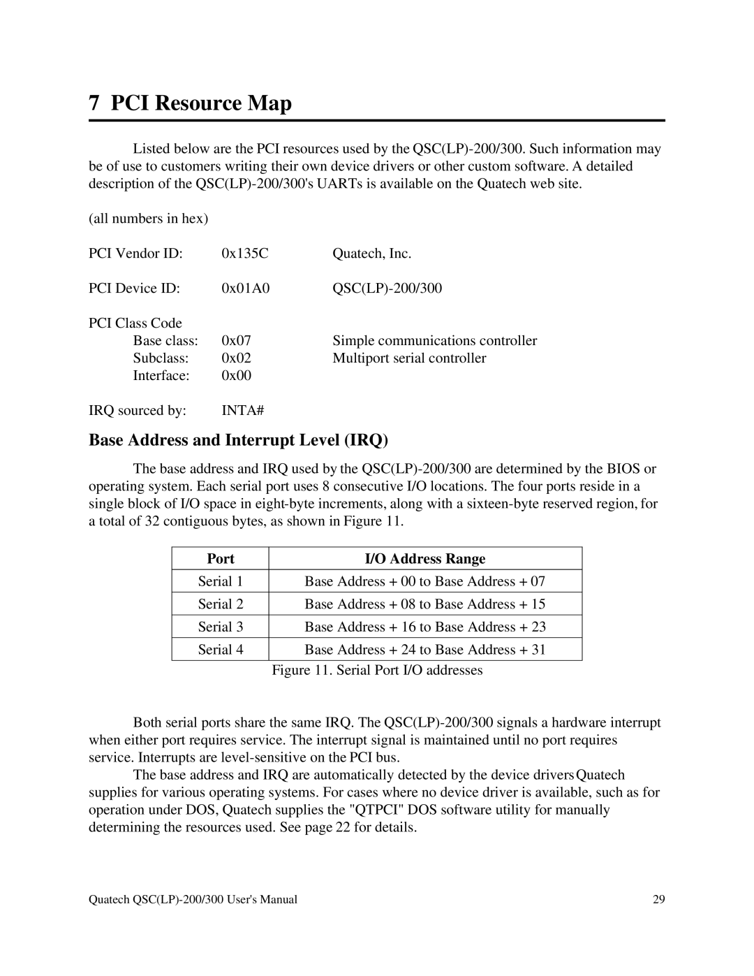
The base address and IRQ used by the
Port | I/O Address Range |
|
|
Serial 1 | Base Address + 00 to Base Address + 07 |
Serial 2 | Base Address + 08 to Base Address + 15 |
|
|
Serial 3 | Base Address + 16 to Base Address + 23 |
|
|
Serial 4 | Base Address + 24 to Base Address + 31 |
|
|
| Figure 11. Serial Port I/O addresses |
Both serial ports share the same IRQ. The
The base address and IRQ are automatically detected by the device driversQuatech supplies for various operating systems. For cases where no device driver is available, such as for operation under DOS, Quatech supplies the "QTPCI" DOS software utility for manually determining the resources used. See page 22 for details.
Quatech | 29 |
