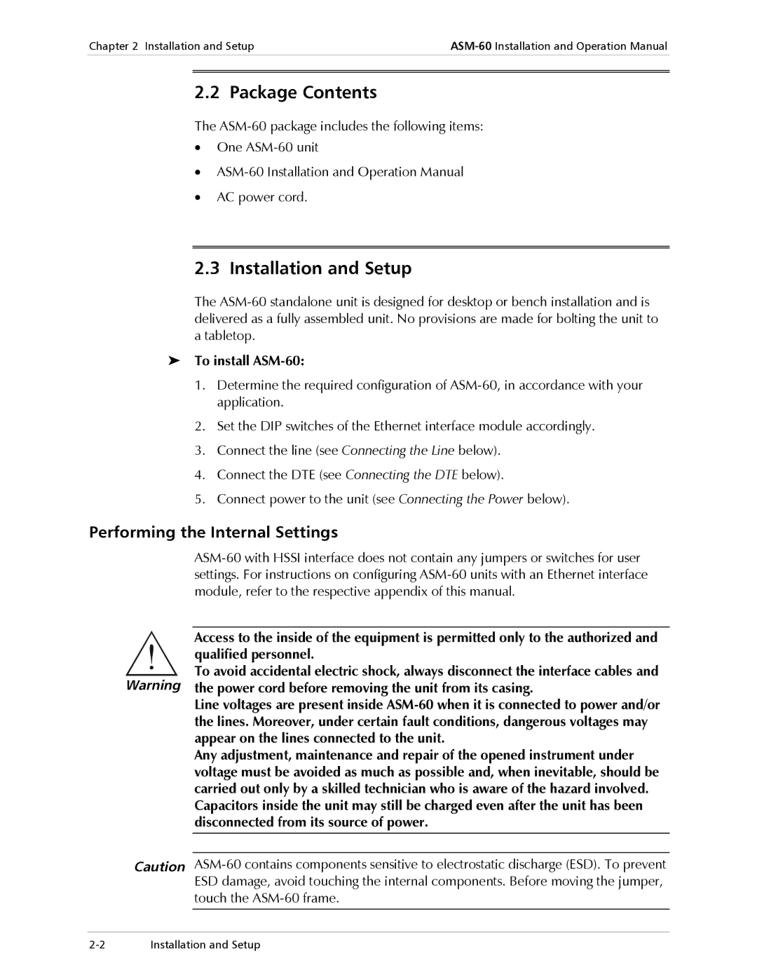
ASM-60 specifications
The RAD Data Communications ASM-60 is a highly advanced access and service management platform designed to streamline the deployment and management of various telecommunications services. It is particularly well-suited for carrier-grade applications, offering a robust solution that meets the demands of modern communication networks. The ASM-60 integrates multiple functionalities, ensuring that service providers can efficiently manage their networks and deliver high-quality services to their customers.One of the standout features of the ASM-60 is its versatility. It supports a wide range of technologies, including Ethernet, TDM, and IP-based services. This adaptability allows service providers to seamlessly integrate legacy systems with newer technologies, ensuring a smooth transition as networks evolve. The platform is equipped to handle both synchronous and asynchronous services, catering to diverse customer needs while maximizing operational efficiency.
Reliability is paramount in telecommunications, and the ASM-60 excels in this regard. It boasts built-in redundancy features, ensuring continuous operation even in the event of a hardware failure. The platform is designed with hot-swappable components, allowing for maintenance and upgrades without disrupting service. This characteristic makes it an ideal choice for mission-critical applications that require uninterrupted service delivery.
In terms of scalability, the ASM-60 offers a comprehensive solution for growing networks. With its modular design, service providers can easily expand their infrastructure as demand increases. This scalability ensures that organizations can effectively respond to changing market conditions and customer requirements, facilitating long-term growth.
Another significant aspect of the ASM-60 is its advanced management capabilities. The platform is equipped with a user-friendly interface that simplifies configuration, monitoring, and troubleshooting tasks. It supports various management protocols, including SNMP and Command Line Interface (CLI), enabling seamless integration with existing network management systems.
Security is also a critical consideration in the design of the ASM-60. It features multiple layers of security, including encryption and authentication protocols, to safeguard sensitive data. This commitment to security helps service providers maintain the integrity and confidentiality of their customers’ information.
In conclusion, the RAD Data Communications ASM-60 is a powerful access and service management platform that meets the diverse needs of modern telecommunications networks. With its versatility, reliability, scalability, advanced management capabilities, and robust security features, the ASM-60 is an ideal choice for service providers looking to enhance their operational efficiency and deliver top-notch services to their customers.

