1. INDEX TO PARTS AND CONTROLS
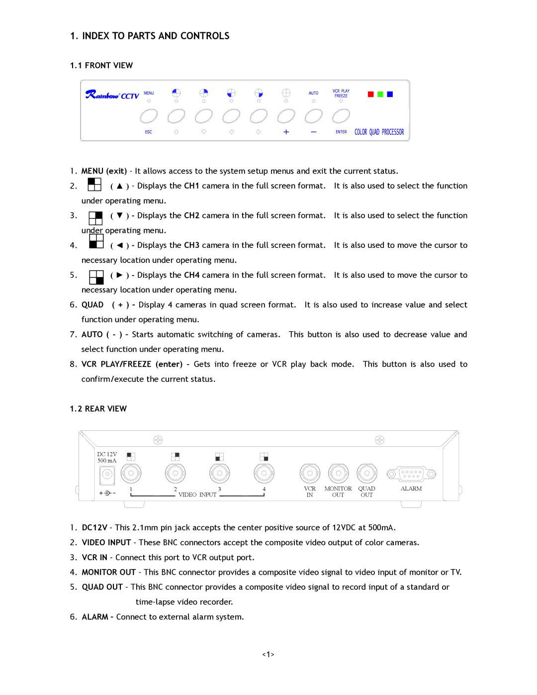
1.1 FRONT VIEW
R
1.MENU (exit) - It allows access to the system setup menus and exit the current status.
2. ![]() ( ▲ ) - Displays the CH1 camera in the full screen format. It is also used to select the function under operating menu.
( ▲ ) - Displays the CH1 camera in the full screen format. It is also used to select the function under operating menu.
3.( ▼ ) - Displays the CH2 camera in the full screen format. It is also used to select the function under operating menu.
4.( ◄ ) - Displays the CH3 camera in the full screen format. It is also used to move the cursor to necessary location under operating menu.
5.( ► ) - Displays the CH4 camera in the full screen format. It is also used to move the cursor to necessary location under operating menu.
6. QUAD ( + ) – Display 4 cameras in quad screen format. It is also used to increase value and select function under operating menu.
7.AUTO ( - ) – Starts automatic switching of cameras. This button is also used to decrease value and select function under operating menu.
8.VCR PLAY/FREEZE (enter) - Gets into freeze or VCR play back mode. This button is also used to confirm/execute the current status.
1.2 REAR VIEW
DC 12V 500 mA
1 | 2 | 3 | 4 | VCR | MONITOR | QUAD | ALARM |
|
| VIDEO INPUT |
| IN | OUT | OUT |
|
1.DC12V – This 2.1mm pin jack accepts the center positive source of 12VDC at 500mA.
2.VIDEO INPUT – These BNC connectors accept the composite video output of color cameras.
3.VCR IN – Connect this port to VCR output port.
4.MONITOR OUT – This BNC connector provides a composite video signal to video input of monitor or TV.
5.QUAD OUT – This BNC connector provides a composite video signal to record input of a standard or
6.ALARM – Connect to external alarm system.
<1>