Electrical Connection
The cooker must be installed by a qualified electrician, in accordance with all relevant British Standards/Codes of Practice (in particular BS 7671), or with the relevant national and local regulations.
WARNING: THE APPLIANCE MUST BE EARTHED.
Note: The cooker must be connected to the correct electrical supply as stated on the voltage label on the cooker, through a suitable cooker control unit incorporating a double pole switch, having a contact separation of at least 3mm in all poles.
The cooker must not be connected to an ordinary domestic power point.
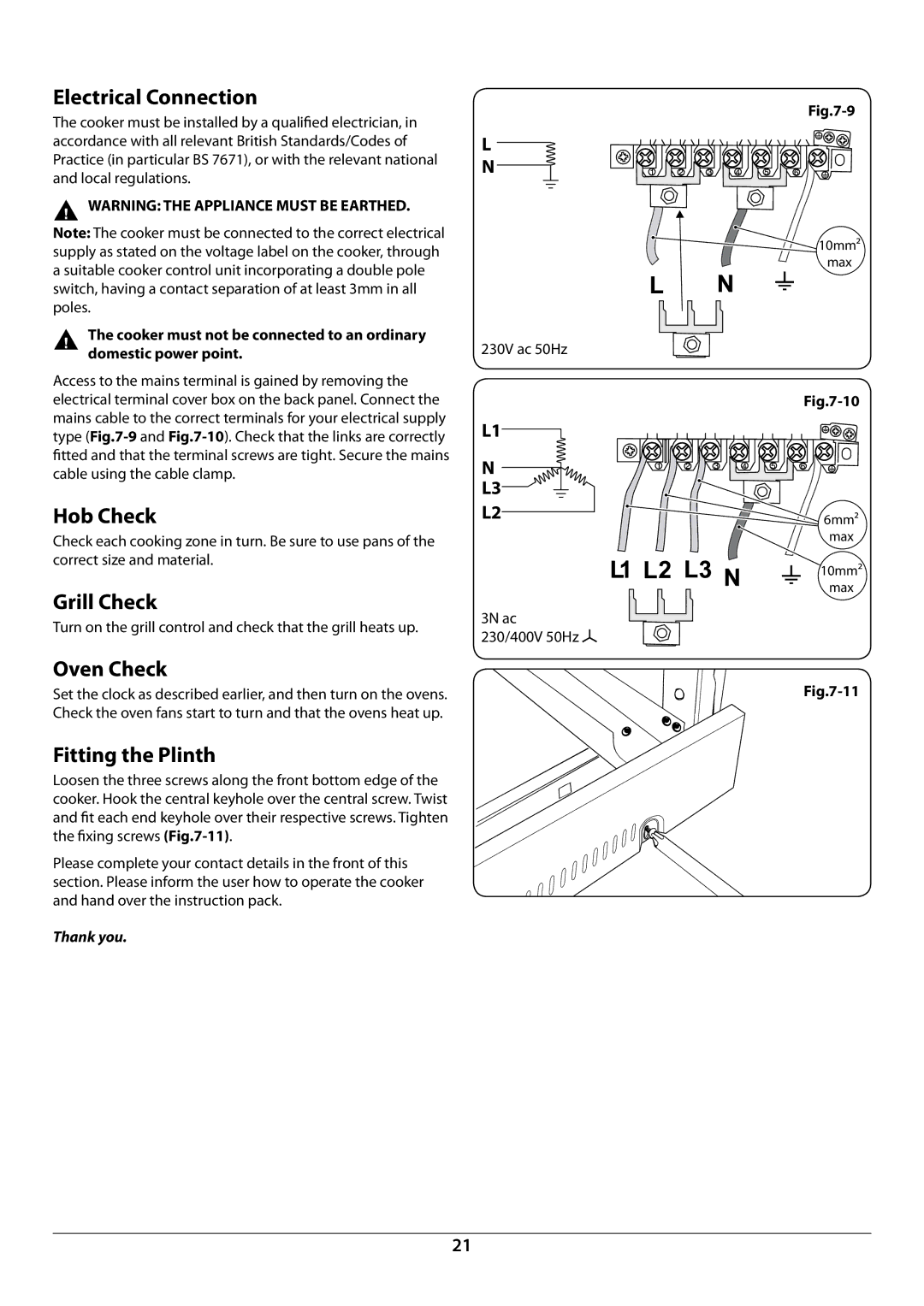
Access to the mains terminal is gained by removing the electrical terminal cover box on the back panel. Connect the mains cable to the correct terminals for your electrical supply type
Hob Check
Check each cooking zone in turn. Be sure to use pans of the correct size and material.
Grill Check
Turn on the grill control and check that the grill heats up.
Oven Check
Set the clock as described earlier, and then turn on the ovens. Check the oven fans start to turn and that the ovens heat up.
�
�
�����
���
������������
��
�
��
�� | ���� |
| |
| ��� |
�����
���
�����
�������������![]()
Fitting the Plinth
Loosen the three screws along the front bottom edge of the cooker. Hook the central keyhole over the central screw. Twist and fit each end keyhole over their respective screws. Tighten the fixing screws
Please complete your contact details in the front of this section. Please inform the user how to operate the cooker and hand over the instruction pack.
Thank you.
21