CAUTION: The heater and its manual shut off valve must be disconnected from the gas supply during any pressure testing of that system at test pressures in excess of 1/2 PSIG(3.45 KPA). Dissipate test pressure in the gas supply line before reconnecting the heater and its manual shut off valve to gas supply line. FAILURE TO FOLLOW THIS PROCEDURE MAY DAMAGE THE GAS VALVE. OVER PRESSURED GAS VALVES ARE NOT COVERED BY WARRANTY. The heater and its gas connections shall be leak tested before placing the appliance in operation. Use soapy water for leak test DO NOT use open flame.
NOTE: Do not use teflon tape on gas line pipe thread. A flexible sealant suitable for use with Natural and Propane gases is recommended.
GAS |
|
|
|
| Inches | W.C. | Regulator |
| Min. | Max. | Setting |
Natural | 7.0 | 10.5 | 4.0 |
Propane | 12.0 | 13.0 | 11.0 |
Note: Do not exceed maximum inlet gas pressure. The minimum value shown is for input adjustment.
GAS PRESSURE REGULATOR
The gas valve is provided with pressure taps to measure gas pressure upstream of the gas valve and downstream which is the same as the manifold pressure.
The gas pressure regulator is preset and sealed at 4" W.C. for natural gas, and 11" W.C. for propane gas. Between the gas valve and the burners is a 1/8" pipe plug. The pressure at this point, taken with a manometer, should be about 3.7" W.C. natural gas and 10.5" W.C. propane gas. Lo NOx models should be 3.9" W.C. natural
gas only. If an adjustment is needed, remove seal and turn adjustment screw clockwise![]() to increase pressure
to increase pressure
or counterclockwise ![]() to decrease pressure.
to decrease pressure.
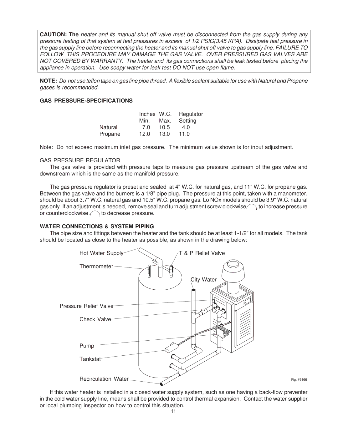
WATER CONNECTIONS & SYSTEM PIPING
The pipe size and fittings between the heater and the tank should be at least
Hot Water Supply | T & P Relief Valve |
Thermometer
City Water
Pressure Relief Valve
Check Valve
Pump
Tankstat
Recirculation Water | Fig. #9166 |
If this water heater is installed in a closed water supply system, such as one having a
11