399B-2339B specifications
The Raypak 399B-2339B is a notable pool heater that stands out in the competitive market of heating solutions, particularly aimed at residential and commercial swimming pools and spas. Designed for efficiency and reliability, the Raypak 399B-2339B integrates advanced technology to deliver a comfortable swimming experience, safeguarding users against fluctuating outdoor temperatures.One of the primary features of the Raypak 399B-2339B is its robust design, built to withstand the rigors of outdoor environments. With a durable cabinet made from corrosion-resistant materials, it ensures longevity and resistance to various weather conditions. This heater boasts a compact footprint, making it an ideal choice for properties with limited installation space.
A standout characteristic of this model is its energy efficiency. The Raypak 399B-2339B utilizes a high-efficiency gas burner, allowing it to heat water quickly while consuming less fuel. This efficiency not only reduces operational costs but also aligns with environmentally conscious practices, making it an appealing choice for eco-friendly users.
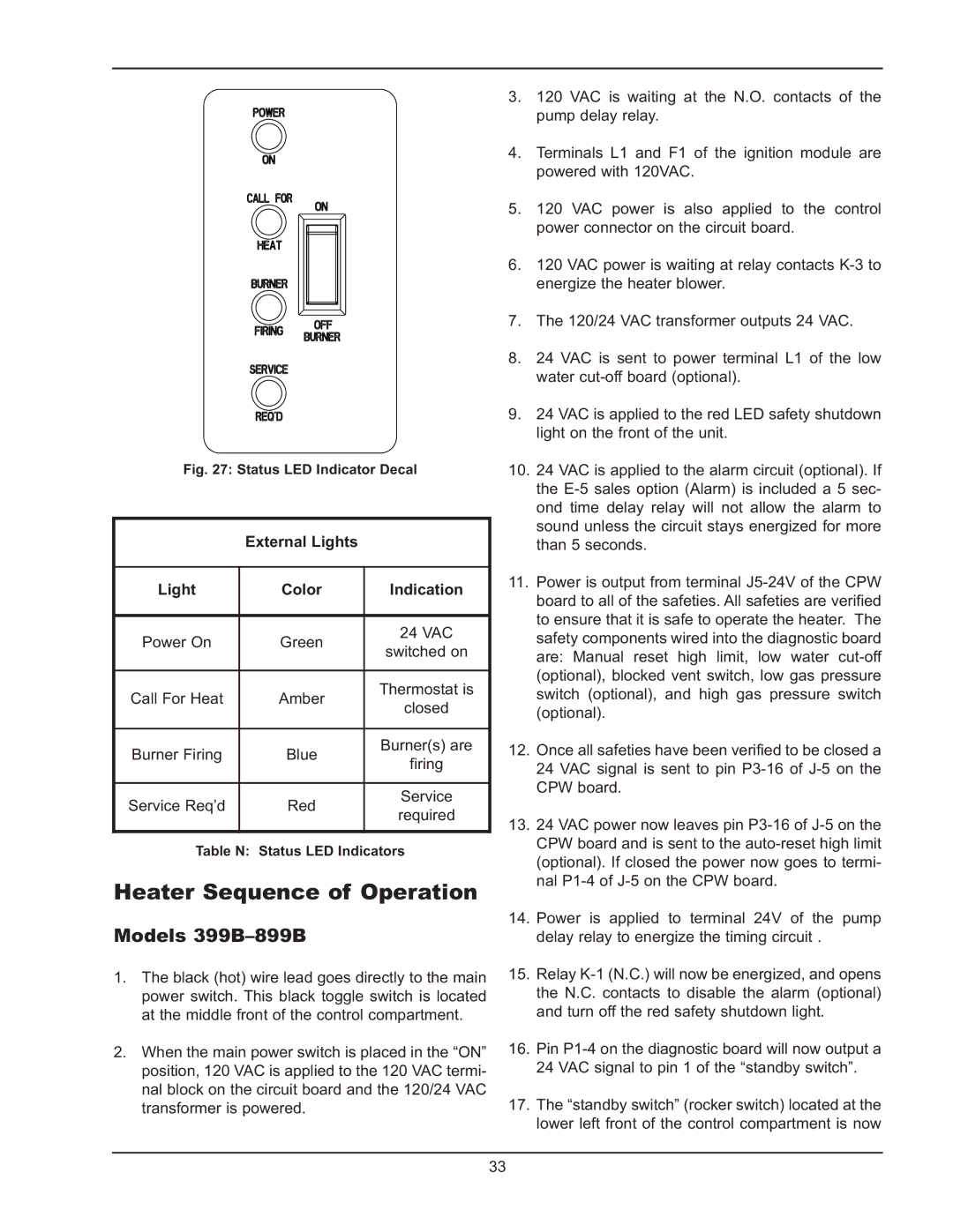
Equipped with innovative technologies, this heater offers both digital controls and diagnostic capabilities. The user-friendly digital display allows for precise temperature control and easy monitoring of the heater's performance. Additionally, the built-in diagnostics feature alerts users to any operational issues, ensuring timely maintenance and minimizing downtime.
The Raypak 399B-2339B is compatible with both natural gas and propane, providing versatility in energy sources. This adaptability can be particularly beneficial for those seeking to switch fuel types or utilize available resources. Moreover, its low NOx emissions make it compliant with stringent environmental regulations, contributing to cleaner air and a healthier ecosystem.
In terms of heating capacity, the Raypak 399B-2339B boasts a powerful output, efficiently heating large bodies of water. This performance makes it suitable for various applications, from residential pools to commercial aquatic centers, ensuring that swimming enjoyment is never compromised due to cold water.
The unit also features a built-in water hydraulics system that optimizes water circulation, preventing overheating and prolonging the lifespan of the heater. Furthermore, the Raypak engineering team has ensured that the installation process is straightforward, with clear guidelines and necessary plumbing fittings provided.
In summary, the Raypak 399B-2339B is a top-tier pool heater that offers durability, energy efficiency, advanced technology, and versatile fuel compatibility. Its high performance and user-friendly features make it a reliable investment for anyone looking to enhance their swimming experience.

