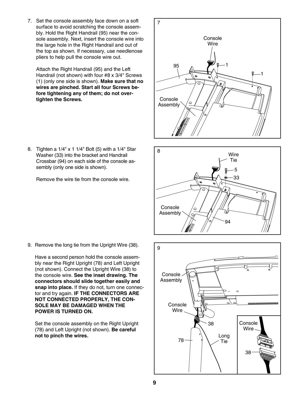
7. Set the console assembly face down on a soft | 7 |
| |
surface to avoid scratching the console assem- |
| ||
|
| ||
bly. Hold the Right Handrail (95) near the con- | Console | ||
sole assembly. Next, insert the console wire into | |||
the large hole in the Right Handrail and out of | Wire |
| |
the top as shown. If necessary, use needlenose |
|
| |
pliers to help pull the console wire out. |
|
| |
Attach the Right Handrail (95) and the Left | 95 | 1 | |
| 1 | ||
Handrail (not shown) with four #8 x 3/4" Screws |
| ||
(1) (only one side is shown). Make sure that no |
|
| |
wires are pinched. Start all four Screws be- |
|
| |
fore tightening any of them; do not over- |
|
| |
tighten the Screws. | Console |
| |
| Assembly |
| |
8. Tighten a 1/4" x 1 1/4" Bolt (5) with a 1/4" Star | 8 | Wire | |
Washer (33) into the bracket and Handrail | |||
| |||
Crossbar (94) on each side of the console as- |
| Tie | |
sembly (only one side is shown). |
| 5 | |
|
| ||
Remove the wire tie from the console wire. |
| 33 | |
|
| ||
| Console |
| |
| Assembly |
| |
|
| 94 | |
9. Remove the long tie from the Upright Wire (38). | 9 |
| |
|
| ||
Have a second person hold the console assem- |
|
| |
bly near the Right Upright (78) and Left Upright |
|
| |
(not shown). Connect the Upright Wire (38) to | Console |
| |
the console wire. See the inset drawing. The |
| ||
connectors should slide together easily and | Assembly |
| |
snap into place. If they do not, turn one connec- |
|
| |
tor and try again. IF THE CONNECTORS ARE |
|
| |
NOT CONNECTED PROPERLY, THE CON- | Console |
| |
SOLE MAY BE DAMAGED WHEN THE |
| ||
POWER IS TURNED ON. | Wire |
| |
Set the console assembly on the Right Upright | 38 | Console | |
(78) and Left Upright (not shown). Be careful |
| Wire | |
not to pinch the wires. | 78 | Long | |
| Tie | ||
|
| 38 | |
| 9 |
| |