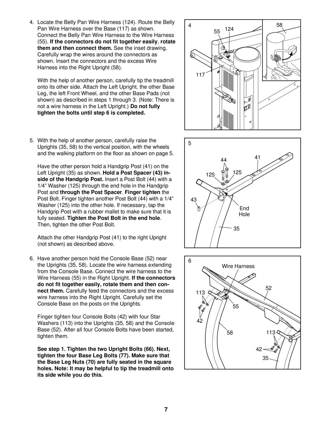
4. Locate the Belly Pan Wire Harness (124). Route the Belly | 4 | 58 | ||
Pan Wire Harness over the B | ase (117) as shown. | |||
| 55 124 | |||
Connect the Belly Pan Wire Harness to the Wire Harness |
|
| ||
(55)If. the connectors do not fit together easily | ,rotate |
| ||
them and then connect them. | See the inset drawing. |
|
| |
Carefully wrap the wires around the connectors as |
|
| ||
shown. Insert the connectors and the excess Wire |
|
| ||
Harness into the Right Upright (58). |
|
|
| |
With the help of another person, carefully tip the treadmill |
| 117 |
|
| ||
|
|
|
| |||
onto its other side. Attach the Left Upright, the other Base |
|
|
| |||
Leg, the left Front Wheel, and the other Base Pads (not |
|
|
|
| ||
shown) as described in steps 1 through 3. (Note: There is |
|
|
|
| ||
not a wire harness in the Left Upright.) | Do not fully |
|
|
| ||
tighten the bolts until step 6 is completed. |
|
|
|
| ||
5. With the help of another person, carefully raise the |
| 5 |
|
| ||
Uprights (35, 58) to the vertical position, with the wheels |
|
| ||||
|
|
| ||||
and the walking platform on the floor as shown on page 5. |
|
|
| 41 | ||
|
|
|
|
| 44 | |
|
|
|
|
|
| |
Have the other person hold a Handgrip Post (41) on the |
|
| 125 |
| ||
Left Upright (35) as shown. | Hold a Post Spacer (43) in- | 125 |
| |||
side of the Handgrip Post. | Insert a Post Bolt (44) with a |
|
| |||
|
|
| ||||
1/4” Washer (125) through the end hole in the Handgrip |
|
|
|
| ||
Post and | through the Post Spacer | . Finger tighten | the |
|
| |
Post Bolt. Finger tighten another Post Bolt (44) with a 1/4” | 43 |
|
| |||
Washer (125) into the other hole. If necessary, tap the |
|
| End |
| ||
Handgrip Post with a rubber mallet to make sure that it is |
|
|
| |||
|
| Hole |
| |||
fully seated. | Tighten the Post Bolt in the end hole |
| . |
| ||
|
|
| ||||
Then, tighten the other Post Bolt. |
|
|
| 35 |
| |
|
|
|
|
|
| |
Attach the other Handgrip Post (41) to the right Upright |
|
|
|
| ||
(not shown) as described above. |
|
|
|
|
| |
6. Have another person hold the Console Base (52) near |
| 6 |
|
| ||
the Uprights (35, 58). Locate the wire harness extending | Wire Harness |
| ||||
|
| |||||
from the Console Base. Connect the wire harness to the |
|
|
|
| ||
Wire Harness (55) in the Right Upright. | If the connectors |
|
|
| ||
do not fit together easily, rotate them and then con- |
|
|
| 52 | ||
nect them. | Carefully feed the connectors and the excess | 113 |
| |||
|
| |||||
wire harness into the Right Upright. Carefully set the |
|
|
| |||
|
|
|
| |||
Console Base on the posts on the Uprights. |
|
| 55 |
| ||
|
|
|
|
|
| |
Finger tighten four Console Bolts (42) with four Star |
| 42 |
|
| ||
Washers (113) into the Uprights (35, 58) and the Console |
|
| ||||
|
|
| ||||
Base (52). After all four Console Bolts have been started, |
| 58 | 113 | |||
tighten them. |
|
|
|
| ||
|
|
|
|
|
| |
See step 1. Tighten the two Upright Bolts (66). Next, |
|
|
| 42 | ||
tighten the four Base Leg Bolts (77). Make sure that |
|
|
| 35 | ||
the Base Leg Nuts (70) are fully seated in the square |
|
|
| |||
|
|
|
| |||
holes. Note: It may be helpful to tip the treadmill onto |
|
|
|
| ||
its side while you do this. |
|
|
|
|
| |
|
|
|
| 7 |
|
|
