Note – The factory has configured the service processor hardware and firmware on your server with the most common settings used in the field. You may not need to change these defaults.
See the Embedded Lights Out Manager (ELOM) Administration Guide for detailed information.
Connecting the Cables
Connect the power and data cables from the server back panel to your system.
Connector Locations
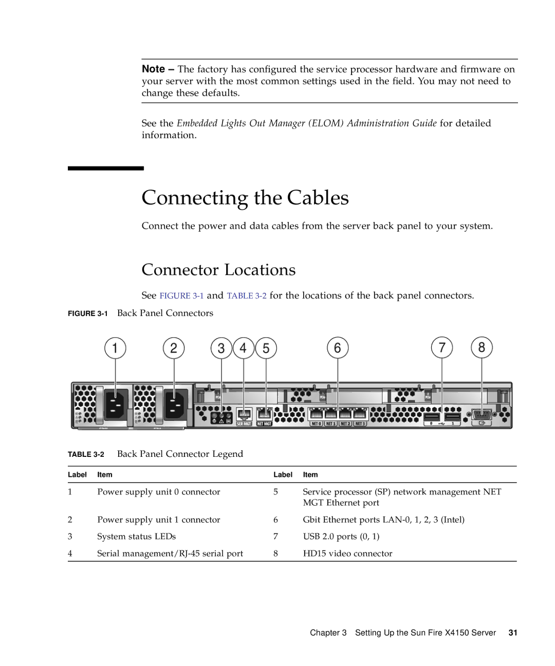
See FIGURE 3-1 and TABLE 3-2 for the locations of the back panel connectors.
FIGURE 3-1 Back Panel Connectors
TABLE 3-2 Back Panel Connector Legend
Label | Item | Label | Item |
|
|
|
|
1 | Power supply unit 0 connector | 5 | Service processor (SP) network management NET |
|
|
| MGT Ethernet port |
2 | Power supply unit 1 connector | 6 | Gbit Ethernet ports |
3 | System status LEDs | 7 | USB 2.0 ports (0, 1) |
4 | Serial | 8 | HD15 video connector |
|
|
|
|
Chapter 3 Setting Up the Sun Fire X4150 Server 31