INSTALLATION
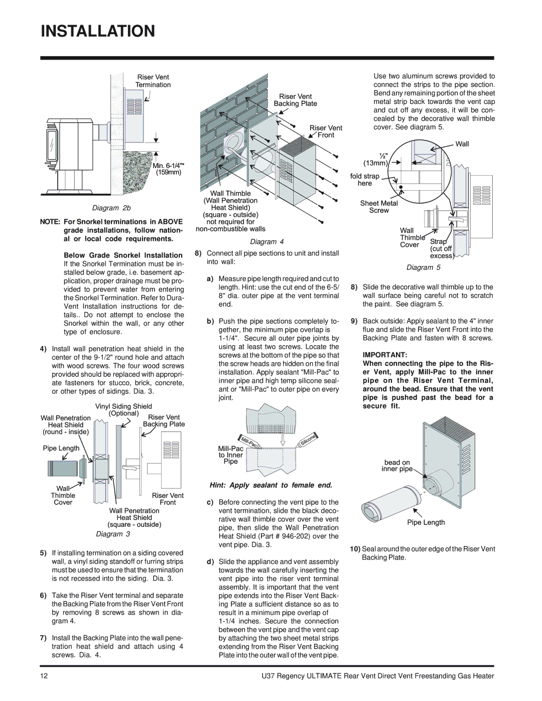
Use two aluminum screws provided to connect the strips to the pipe section. Bend any remaining portion of the sheet metal strip back towards the vent cap and cut off any excess, it will be con- cealed by the decorative wall thimble
cover. See diagram 5.
Diagram 2b
NOTE: For Snorkel terminations in ABOVE grade installations, follow nation- al or local code requirements.
Below Grade Snorkel Installation If the Snorkel Termination must be in- stalled below grade, i.e. basement ap- plication, proper drainage must be pro- vided to prevent water from entering the Snorkel Termination. Refer to Dura- Vent Installation instructions for de- tails.. Do not attempt to enclose the Snorkel within the wall, or any other type of enclosure.
4)Install wall penetration heat shield in the center of the
Diagram 4
8)Connect all pipe sections to unit and install into wall:
a)Measure pipe length required and cut to length. Hint: use the cut end of the
b)Push the pipe sections completely to- gether, the minimum pipe overlap is
Diagram 5
8)Slide the decorative wall thimble up to the wall surface being careful not to scratch the paint. See diagram 5.
9)Back outside: Apply sealant to the 4" inner flue and slide the Riser Vent Front into the Backing Plate and fasten with 8 screws.
IMPORTANT:
When connecting the pipe to the Ris- er Vent, apply
Diagram 3
5)If installing termination on a siding covered wall, a vinyl siding standoff or furring strips must be used to ensure that the termination is not recessed into the siding. Dia. 3.
6)Take the Riser Vent terminal and separate the Backing Plate from the Riser Vent Front by removing 8 screws as shown in dia- gram 4.
7)Install the Backing Plate into the wall pene- tration heat shield and attach using 4 screws. Dia. 4.
Hint: Apply sealant to female end.
c)Before connecting the vent pipe to the vent termination, slide the black deco- rative wall thimble cover over the vent pipe, then slide the Wall Penetration Heat Shield (Part #
d)Slide the appliance and vent assembly towards the wall carefully inserting the vent pipe into the riser vent terminal assembly. It is important that the vent pipe extends into the Riser Vent Back- ing Plate a sufficient distance so as to result in a minimum pipe overlap of
10)Seal around the outer edge of the Riser Vent Backing Plate.
12 | U37 Regency ULTIMATE Rear Vent Direct Vent Freestanding Gas Heater |