Page
What’s included
MS249R, CMS249R Bronze MS249RW, CMS249RW White
How it works
What you need
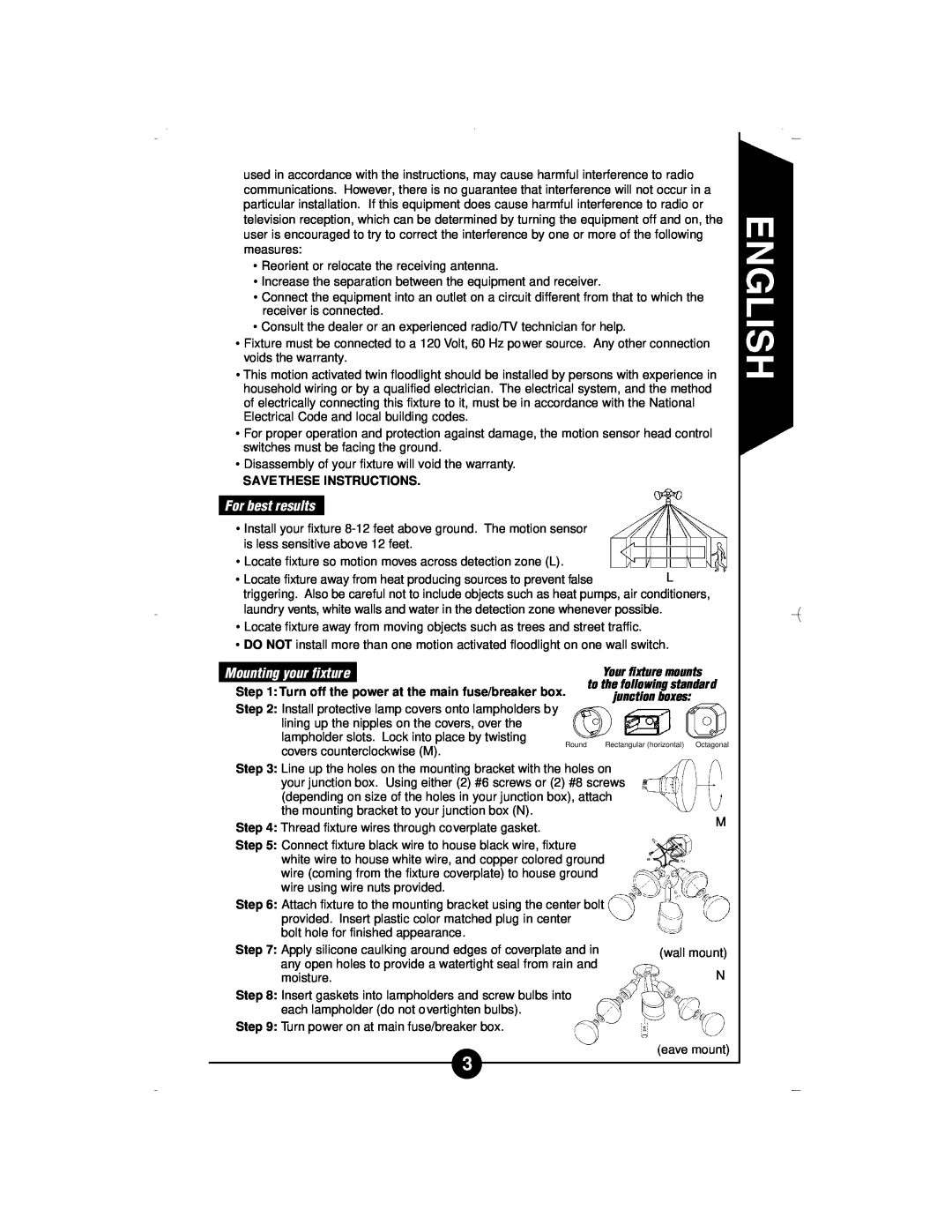
For best results
SAVE THESE INSTRUCTIONS
Your fixture mounts
House code selections on sensor head O
How to operate your fixture
Indoor alarm/lamp control module operation guide P
Switch setting
Lamp control
Alarm tone sequence
Your indoor alarm/lamp control module is ready to
plug in and use. There is no installation required
Mode of
How to select your desired feature of the motion detector
Set slide switch
How to set
continued
What to do if
Two year limited warranty
There are no express warranties except as described above
Qué se incluye
MS249R, CMS249R Bronce MS249RW, CMS249RW Blanco
Cómo funciona
Qué se requiere
Para obtener mejores resultados
Montaje de su portalámparas
GUARDE ESTAS INSTRUCCIONES
Operación de su portalámparas
Tonos
NOTA El módulo de control de la alarma/lámpara Control de
Selección de los códigos de casa en el cabezal del sensor O
Posiciones del
Cómo elegir la función deseada del detector de movimiento
Sequencia del tono de la alarma
Control de la lámpara
Control manual de la lámpara
deseado
continuación
Qué hacer si
En caso positivo, asegúrese que el conmutador en la pared está
La lámpara interior se prendera solamente cuando las luces exte
Dos años de garantía limitada
Patentes 5,381,3235,515,252y otras patentes pendientes
Impreso en China
Ce qui est compris dans cet ensemble
MS249R, CMS249R Bronze MS249RW, CMS249RW Blanc
Comment votre projecteur fonctionne
Ce dont vous avez besoin
CONSERVER CES INSTRUTCIONS
Pour de meilleurs résultats
Montage du dispositif
trois types de boîte de connexion
REMARQUE La température peut affecter la sensibilité du détecteur
Comment faire fonctionner votre dispositif
Etape
H . . . . . 18 m ou plus portée maximale
intérieure activera l’alarme sonore et allumera la
branchée, d’une puissance pouvant atteindre 300 watts . volume
Tout modèle extérieur Regent MS249 configuré
avec le même code domestique que lampe/alarme
suite
Séquence de la tonalité d’alarme
Contrôle de la lampe intérieure
Contrôle manuel de la lampe intérieure
Que faire si
suite
LA LAMPE INTÉRIEURE NE S’ÉTEINT PAS
L’ALARME INTÉRIEURE NE SE FAIT PAS ENTENDRE
Garantie limitée de deux ans
LA LAMPE INTÉRIEURE NE S’ALLUME PAS
Page
REMARQUES
Brevets 5,381,3235,515,252et d’autres brevets déposés
Imprimé en Chine 6/06