Thermal Expansion
As water is heated, it expands (thermal expansion). In a closed system the volume of water will grow when it is heated. As the volume of water grows there will be a corresponding increase in water pressure due to thermal expansion. Thermal expansion can cause premature tank failure (leakage). This type of failure is not covered under the limited warranty. Thermal expansion can also cause intermittent Temperature-Pressure Relief Valve operation: water discharged from valve due to excessive pressure build up. This condition is not covered under the limited warranty. The Temperature-Pressure Relief Valve is not intended for constant relief of thermal expansion.
A properly sized thermal expansion tank must be installed on all closed systems to control the harmful effects of thermal expansion. Contact a local plumbing service agency to have a thermal expansion tank installed.
NOTE: To protect against untimely corrosion of hot and cold water fittings, it is strongly recommended that di-electric unions or couplings be installed on this water heater when connected to copper pipe.
All gas piping must comply with local codes and ordinances or with the National Fuel Gas Code (ANSI Z223.1/ NFPA-54). Copper and brass tubing and fittings (except tin lined copper tubing) should not be used.
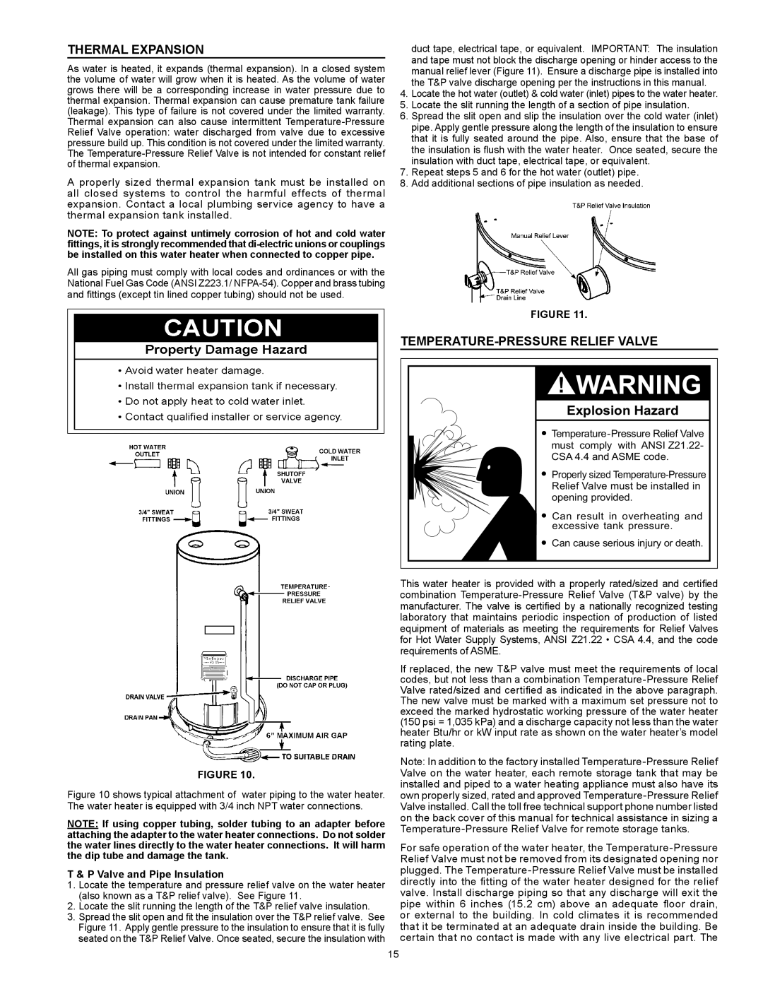
FIGURE 10.
Figure 10 shows typical attachment of water piping to the water heater. The water heater is equipped with 3/4 inch NPT water connections.
NOTE: If using copper tubing, solder tubing to an adapter before attaching the adapter to the water heater connections. Do not solder the water lines directly to the water heater connections. It will harm the dip tube and damage the tank.
T & P Valve and Pipe Insulation
1.Locate the temperature and pressure relief valve on the water heater
(also known as a T&P relief valve). See Figure 11.
2.Locate the slit running the length of the T&P relief valve insulation.
3.Spread the slit open and fit the insulation over the T&P relief valve. See
Figure 11. Apply gentle pressure to the insulation to ensure that it is fully seated on the T&P Relief Valve. Once seated, secure the insulation with
duct tape, electrical tape, or equivalent. IMPORTANT: The insulation and tape must not block the discharge opening or hinder access to the
manual relief lever (Figure 11). Ensure a discharge pipe is installed into
the T&P valve discharge opening per the instructions in this manual.
4.Locate the hot water (outlet) & cold water (inlet) pipes to the water heater.
5.Locate the slit running the length of a section of pipe insulation.
6.Spread the slit open and slip the insulation over the cold water (inlet) pipe. Apply gentle pressure along the length of the insulation to ensure that it is fully seated around the pipe. Also, ensure that the base of the insulation is flush with the water heater. Once seated, secure the insulation with duct tape, electrical tape, or equivalent.
7.Repeat steps 5 and 6 for the hot water (outlet) pipe.
8.Add additional sections of pipe insulation as needed.
FIGURE 11.
Temperature-Pressure Relief Valve
Explosion Hazard
 Temperature-Pressure Relief Valve must comply with ANSI Z21.22- CSA 4.4 and ASME code.
 Properly sized Temperature-Pressure Relief Valve must be installed in opening provided.
 Can result in overheating and excessive tank pressure.
 Can cause serious injury or death.
This water heater is provided with a properly rated/sized and certified combination Temperature-Pressure Relief Valve (T&P valve) by the manufacturer. The valve is certified by a nationally recognized testing laboratory that maintains periodic inspection of production of listed equipment of materials as meeting the requirements for Relief Valves for Hot Water Supply Systems, ANSI Z21.22 • CSA 4.4, and the code requirements of ASME.
If replaced, the new T&P valve must meet the requirements of local codes, but not less than a combination Temperature-Pressure Relief Valve rated/sized and certified as indicated in the above paragraph. The new valve must be marked with a maximum set pressure not to exceed the marked hydrostatic working pressure of the water heater (150 psi = 1,035 kPa) and a discharge capacity not less than the water heater Btu/hr or kW input rate as shown on the water heater’s model rating plate.
Note: In addition to the factory installed Temperature-Pressure Relief Valve on the water heater, each remote storage tank that may be installed and piped to a water heating appliance must also have its own properly sized, rated and approved Temperature-Pressure Relief Valve installed. Call the toll free technical support phone number listed on the back cover of this manual for technical assistance in sizing a Temperature-Pressure Relief Valve for remote storage tanks.
For safe operation of the water heater, the Temperature-Pressure Relief Valve must not be removed from its designated opening nor plugged. The Temperature-Pressure Relief Valve must be installed directly into the fitting of the water heater designed for the relief valve. Install discharge piping so that any discharge will exit the pipe within 6 inches (15.2 cm) above an adequate floor drain, or external to the building. In cold climates it is recommended that it be terminated at an adequate drain inside the building. Be certain that no contact is made with any live electrical part. The