Manuals
/
Renesas
/
Computer Equipment
/
Computer Hardware
Renesas
H8S/2615 Series
user manual
Connecting User System Interface Cable to Emulator Station
Models:
H8S/2615 Series
1
15
26
26
Download
26 pages
11.56 Kb
12
13
14
15
16
17
18
19
Install
Warranty
Configuration
Connection Procedures
Safety
Page 15
Image 15
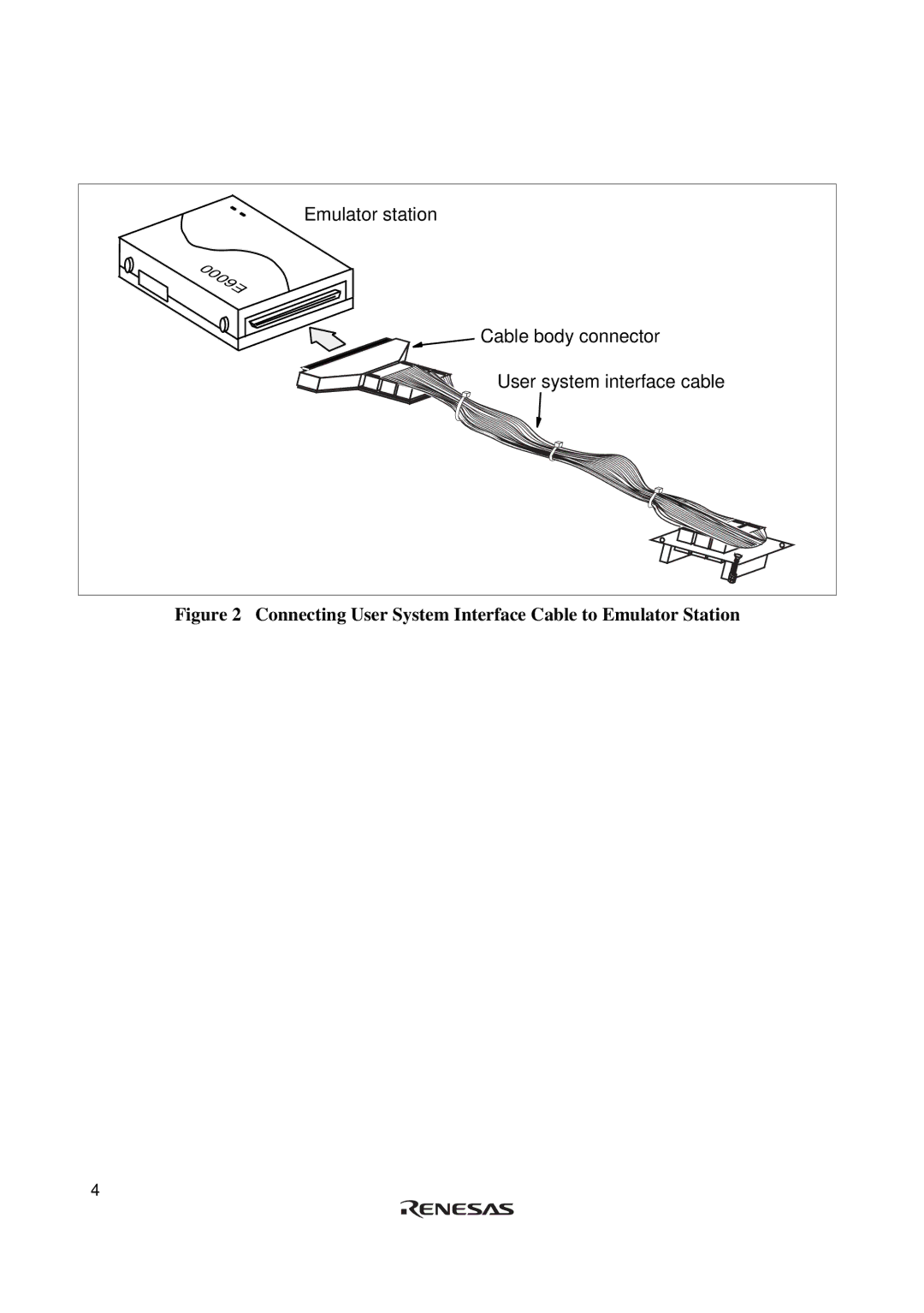
Emulator station
Cable body connector
User system interface cable
Figure 2 Connecting User System Interface Cable to Emulator Station
4
Page 14
Page 16
Page 15
Image 15
Page 14
Page 16
Contents
User’s Manual
Page
Important Information
Limited Warranty
Figures Limited Anticipation of Danger
Safety
Parts
Page
Page
Preface
Contents
HS2615ECH61H User System Interface Cable
Configuration
HS2615ECH61H Components
Connection Procedures
Connecting User System Interface Cable to Emulator Station
Connecting User System Interface Cable to User System
Check the location of pin 1 before inserting
Connecting User System Interface Cable to User System
Fastening Cable Body
Recommended Dimensions for User System Mount Pad
Dimensions for User System Interface Cable Head
Page
Installing the MCU to the User System
Installing MCU to User System
Oscillator Circuit
Verifying Operation
User System Interface Cable Location Example
Top
Page
Image
Contents